Kia Cee'd: ESP(Electronic Stability Program) System / Description and operation
Kia Cee'd JD Service Manual / Brake System / ESP(Electronic Stability Program) System / Description and operation
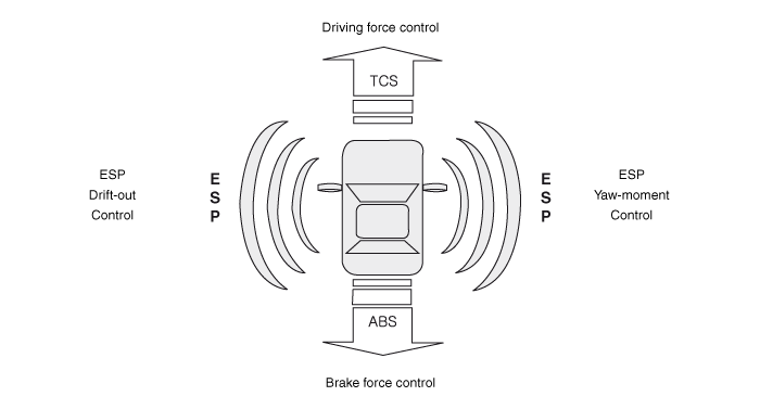
| Description of ESP |
Optimum driving safety now has a name : ESP, the Electronic Stability Program.
ESP recognizes critical driving conditions, such as panic reactions in dangerous
situations, and stabilizes the vehicle by wheel-individual braking and engine
control intervention with no needfor actuating the brake or the gas pedal.
ESP adds a further function known as Active Yaw Control (AYC) to the ABS, TCS,
EBD and ESP functions. Whereas the ABS/TCS function controls wheel slip during
braking and acceleration and, thus, mainly intervenes in the longitudinal dynamics
of the vehicle, active yaw control stabilizes the vehicle about its vertical
axis.
This is achieved by wheel individual brake intervention and adaptation of the
momentary engine torque with no need for any action to be taken by the driver.
ESP essentially consists of three assemblies : the sensors, the electronic control
unit and the actuators.
Of course, the stability control feature works under all driving and operating
conditions. Under certain driving conditions, the ABS/TCS function can be activated
simultaneously with the ESP function in response to a command by the driver.
In the event of a failure of the stability control function, the basic safety
function, ABS, is still maintained.
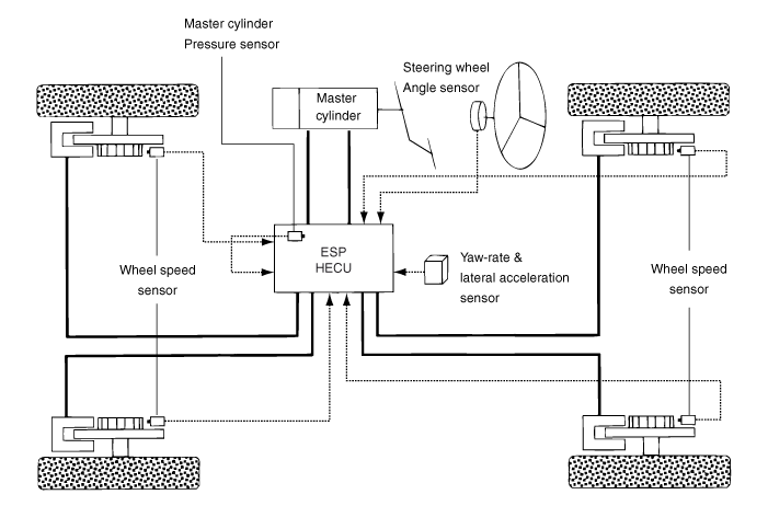
Description of ESP Control
ESP system includes ABS/EBD, TCS and AYC (Active yaw control) function.
ABS/EBD function : The ECU changes the active sensor signal (current shift)
coming from the four wheel sensors to the square waveform.By using the input
of above signals, the ECU calculates the vehicle speed and the acceleration
& deceleration of the four wheels.And, the ECU judges whether the ABS/EBD should
be actuated or not.
TCS function prevents the wheel slip of drive direction by adding the brake
pressure and engine torque reduction via CAN communication.TCS function uses
the wheel speed sensor signal to determine the wheel slip as far as ABS function.
AYC function prevents unstable maneuver of the vehicle. To determine the vehicle
maneuver, AYC function uses the maneuver sensor signals(Yaw Rate Sensor, Lateral
Acceleration Sensor, Steering Wheel Angle Sensor).
If vehicle maneuver is unstable (Over Steer or Under Steer), AYC function applies
the brake pressure on certain wheel, and send engine torque reduction signal
by CAN.
After the key-on, the ECU continually diagnoses the system failure. (self-diagnosis)If
the system failure is detected, the ECU informs driver of the system failure
through the BRAKE/ABS/ESP warning lamp. (fail-safe warning)
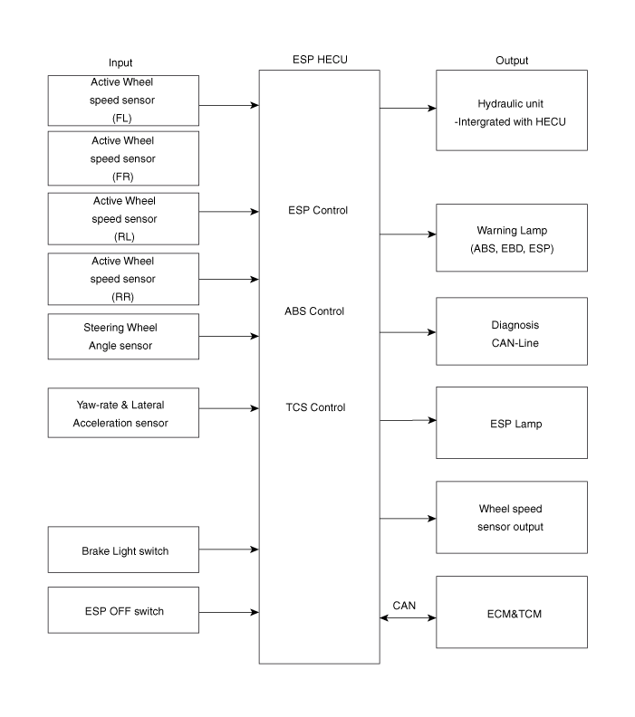
Input and Output Diagram
| ESP Operation Mode |
| 1. |
STEP 1
The ESP analyzes the intention of the driver.
|

| 2. |
STEP 2
It analyzes the movement of the ESP vehicle.
|

| 3. |
STEP 3
The HECU calculates the required strategy, then actuates the appropriate
valves and sents torque control requests via CAN to maintain vehicle
stability.
|
ESP Operation Mode
| 1. |
ESP Non-operation-Normal braking.
|

| 2. |
ESP Increase Mode
|
| 3. |
ESP Hold Mode ( FR is only controlled.)
|
| 4. |
ESP Decrease Mode (FR is only controlled)
|
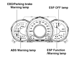
ABS Warning lamp
The active ABS warning lamp indicates the self-test and failure status of the
ABS. The ABS warning lamp shall be on:
| – |
During the initialization phase after IGN ON. (continuously 3 seconds).
|
| – |
In the event of inhibition of ABS functions by failure.
|
| – |
During diagnostic mode.
|
| – |
When the ECU Connector is separated from ECU.
|
EBD/Parking brake warning lamp
The active EBD warning lamp indicates the self-test and failure status of the
EBD. However, in case the Parking Brake Switch is turned on, the EBD warning
lamp is always turned on regardless of EBD functions. The EBD warning lamp shall
be on:
| – |
During the initialization phase after IGN ON. (continuously 3 seconds).
|
| – |
When the Parking Brake Switch is ON or brake fluid level is low.
|
| – |
When the EBD function is out of order .
|
| – |
During diagnostic mode.
|
| – |
When the ECU Connector is separated from ECU.
|
ESP Function/Warning Lamp (ESP System)
The ESP Function/Warning lamp indicates the self-test and failure status of
the ESP.
The ESP Function/Warning lamp operates under the following conditions :
| – |
During the initialization phase after IGN ON. (continuously 3 seconds).
|
| – |
In the event of inhibition of ESP functions by failure.
|
| – |
During dignostic mode.
|
| – |
When the ESP control is operating. (Blinking - 2Hz)
|
ESP OFF Lamp (ESP system)
The ESP OFF lamp indicates the self-test and operating status of the ESP.
The ESP OFF lamp is turned on under the following conditions :
| – |
During the initialization phase after IGN ON. (continuously 3 seconds).
|
| – |
When driver turn off the ESP function by on/off switch.
|
ESP On/Off Switch (ESP system)
| • |
1st stage
The ESP engine control function will stop when the ESP OFF indicator
on the cluster turns on by pressing the ESP OFF button for 0.15 second.
(The brake control function works normally.)
|
| • |
2nd stage
The ESP engine and brake control function will stop when the ESP OFF
indicator on the cluster turns on by pressing the ESP OFF button for
3 seconds.
|
 Components and components location
Components
1. ESP Control Module (HECU)
2. Front Wheel Speed Sensor
3. Rear Wheel Speed Sensor
4. Steering Wheel Angle Sensor
5. Yaw-late & Lat ...
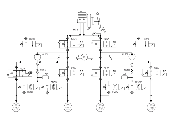
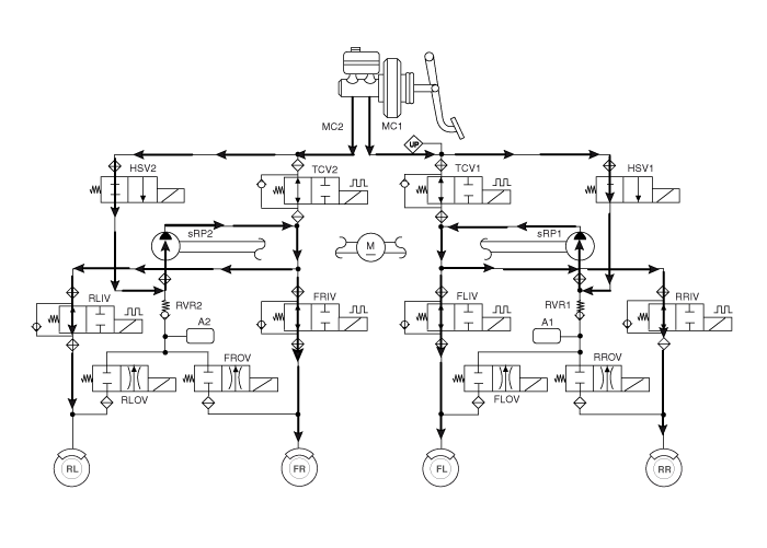
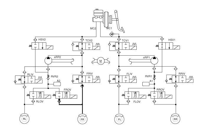
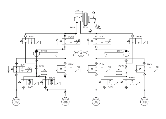
 Schematic diagrams
Circuit Diagram - ESP (1)
Circuit Diagram - ESP (2)
Circuit Diagram - ESP (3)
Circuit Diagram - ESP (4)
ESP Connector Input/ ...
Other information:
Kia Cee'd JD Owners Manual: Non-operating condition
The sensors are located inside of the
rear bumper.
Always keep the rear bumper clean for
the system to work properly.
WARNING
The warning light on the outside
rearview mirror will illuminate
whenever a vehicle is detected at
the rear side by the system.
To avoid accidents, do ...
Kia Cee'd JD Service Manual: General safety information and caution
Precautions
General Precautions
Please read the following precautions carefully before performing the airbag
system service.
Observe the instructions described in this manual, or the airbags could accidentally
deploy and cause damage or injuries.
• ...
© 2017-2026 www.kceed.com
