Kia Cee'd: Button Engine Start System / Description and operation
| Description |
| – |
Human machine interface through a 1-stage button, for terminal switching
and engine start.
|
| – |
Control of external relays for ACC / IGN1 / IGN2 terminal switching
and STARTER, without use of mechanical ignition switch.
|
| – |
Steering column locking with an ESCL device; Monitoring of the vehicle
status to insure safe activation of the ESCL.
|
| – |
Indication of vehicle status through LED or explicit messages on display.
|
| – |
Immobilizer function by LF transponder communication between fob and
start/stop button.
|
| – |
Redundant architecture for high system dependability .
|
| – |
Interface with Low Speed CAN vehicle communication network.
|
| – |
Interface with LIN vehicle communication network depending on platform
.
|
| – |
Steering column locking/unlocking with ESCL.
|
| – |
Switching of ACC / IGN1 / IGN2 terminals.
|
| – |
Control of the STARTER relay BAT line (high side) based on communication
with EMS ECU.
|
| – |
Management of the Immobilizer function.
|
| – |
Management of BES warning function.
|
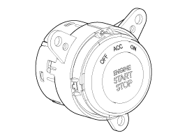
| • |
Control Ignition and engine ON/OFF by Sending signal to IPM.
|
| • |
Display status by LED Lamp ON/OFF. (Amber or Blue)
|
|
No. |
Character lamp |
Conditions |
|
1 |
Indicator Lamp ON |
Door open, Tail lamp ON, ACC, IG ON |
|
2 |
Indicator Lamp 30sec ON → Lamp OFF |
Door close, Tail lamp OFF, IG OFF |
|
3 |
Indicator Lamp OFF |
Remote LOCK, Passive LOCK |
|
4 |
Rheostat at tail lamp ON (Illumination lamp) |
|
|
No. |
Ignition conditions |
Start Button LED status |
|
1 |
IG OFF |
LED OFF |
|
2 |
IG ACC |
Amber color LED ON |
|
3 |
IG ON (Engine OFF) |
Blue color LED ON |
|
4 |
Cranking |
Maintain LED status before cranking |
|
5 |
Engine running |
LED OFF |
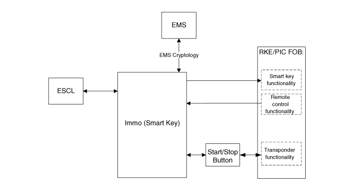
| – |
Non-smart key RKE
|
| – |
SMART KEY FOB
|
| • |
"Start Stop Button (SSB) monitoring",
|
| • |
"Immobilizer communication" (with Engine Management System unit for
immobilizer release),
|
| • |
"ESCL control",
|
| • |
"Authentication server" (Validity of Transponder and in case of Smart
Key option Passive Fob authentication ),
|
| • |
"System consistency monitoring",
|
| • |
"System diagnosis",
|
| • |
Control of display message / warning buzzer .
|

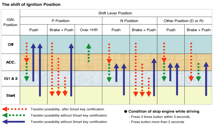
| • |
To activate the power modes ‘Off’, ’Accessory’, ‘Ignition’ and 'Start'
by switching the corresponding terminals
|
| • |
To start the engine
|
| • |
To stop the engine
|
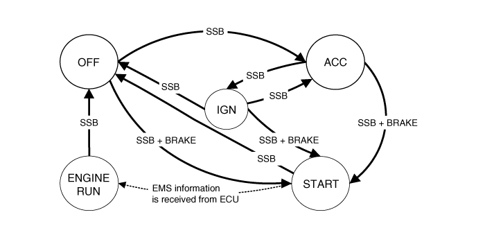
|
System State |
Terminal Status |
ESCL Status |
Engine status |
|
1. OFF - Locked |
OFF |
Locked |
Stopped |
|
2. OFF - Unlocked |
OFF |
Unlocked |
Stopped |
|
3. ACC |
ACC |
Unlocked |
Stopped |
|
4. IGN |
IGN1, IGN2, ACC |
Unlocked |
Stopped |
|
5. Start |
IGN1, Start |
Unlocked |
Cranking |
|
6. IGN - Engine |
IGN1, IGN2, ACC |
Unlocked |
Running (means "self-running") |
|
System State |
Terminal Status |
ESCL Status |
Engine status |
|
1. OFF - UNLOCKED |
OFF |
Unlocked |
Stopped |
|
2. ACC |
ACC |
Unlocked |
Stopped |
|
3. IGN |
IGN1, IGN2, ACC |
Unlocked |
Stopped |
|
4. Start |
IGN1, START with special pattern of activation see Chap 6.2.1 for details
|
Unlocked |
Cranking |
|
5. IGN - Engine |
IGN1, IGN2, ACC |
Unlocked |
Running (means "self-running") |
 Schematic diagrams
Circuit Diagram
...
 Start/Stop Button Components and components location
Component
...
Other information:
Kia Cee'd JD Service Manual: Transmission Control Module (TCM) Repair procedures
Inspection
Transmission Control Module (TCM) Inspection
Procedure
1.
Inspecting TCM ground circuit: Measure the resistance between the TCM
and chassis ground.
(Check the terminal connected to the chassis ground while using the
ba ...
Kia Cee'd JD Owners Manual: MAINTENANCE UNDER SEVERE USAGE CONDITIONS - EXCEPT EUROPE
The following items must be serviced more frequently on cars mainly used
under severe driving conditions.
Refer to the chart below for the appropriate maintenance intervals.
R : Replace
I : Inspect and if necessary, adjust, correct, clean or replace
SEVERE DRIVING CONDITIONS
A : Repeated ...
