Kia Cee'd: Driveshaft Assembly / TJ Joint Repair procedures
| Replacement |
|
| 1. |
Remove the Front Driveshaft.
(Refer to Driveshaft Assembly - “Front Driveshaft”)
|
| 2. |
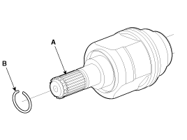
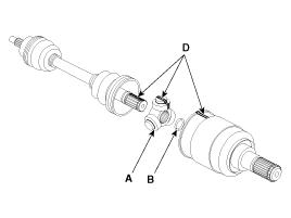
Remove the housing circlip (B) from the driveshaft spline (A).
|
| 3. |
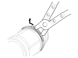
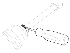
Remove both boot bands from the TJ housing.
|
| 4. |
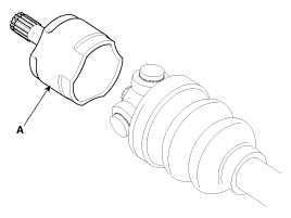
Remove the TJ housing (A).
|
| 5. |
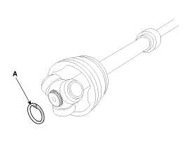
Remove the retainer ring (A) from the shaft.
|
| 6. |
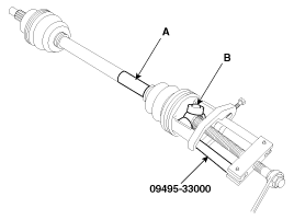
Remove the spider assembly (B) from the driveshaft (A) using the special
tool (09495-33000).
|
| 7. |
Clean the spider assembly.
|
| 8. |
Remove the TJ boot (A).
|
| Inspection |
| 1. |
Check the spider assembly for roller rotation, wear or corrosion.
|
| 2. |
Check the groove inside the joint case for wear or corrosion
|
| 3. |
Check the TJ boots for damage and deterioration.
|
| Installation |
| 1. |
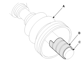
Wrap tape around the driveshaft spline(TJ) to prevent damage to the
boot.
|
| 2. |
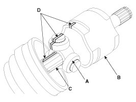
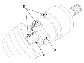
Using the alignment marks (D) made during disassembly as a guide, install
the spider assembly (A) and retainer ring (B) on the driveshaft splines
(C).
|
| 3. |
Add specified grease to the joint boot as much as it was wiped away
at inspection.
|
| 4. |
Install the both boot band.
|
| 5. |
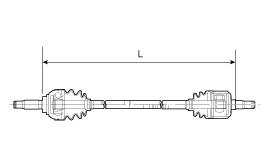
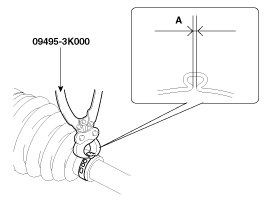
To control the air in the TJ boot, keep the specified distance between
the boot bands when they are tightened.
|
||||||||||||||||||||||||||||||||||||||||||
| 6. |
Using the SST(09495-3K000), secure the TJ boot bands.
|
| 7. |
Install the Front Driveshaft.
(Refer to Driveshaft Assembly - “Front Driveshaft”)
|
 TJ Joint Components and components location
Components
[LH]
1. BJ assembly
2. BJ circlip
3. BJ boot band
4. BJ boot
5. Shaft
6. TJ boot band
7. TJ boot
8. Sp ...
 Dynamic Damper Components and components location
Components
1. BJ
assembly
2. BJ circlip
3. BJ boot band
4. BJ boot
5. Dynamic
damper band
6. Dynamic damper
7. Shaft
8. TJ boo ...
Other information:
Kia Cee'd JD Service Manual: Gear Actuator Motor Repair procedures
Inspection
1.
Turn off the ignition switch.
2.
Disconnect the shift actuator connector (A) and select actuator connector
(B).
3.
Measure the resistance on the gear actuator motor terminal.
...
Ford Escape 2020-2025 Owners Manual: Opening the Liftgate
Press the control button to unlatch the
liftgate and then lift to open.
Note: Be careful when opening or closing
the liftgate in a garage or other enclosed
area to avoid damaging the liftgate.
Note: Do not hang anything, for example a
bike rack, from the glass or liftgate. This
could damage th ...


