Kia Cee'd: ABS(Anti-Lock Brake System) / Schematic diagrams
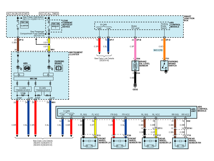
| Circuit Diagram - ABS (1) |

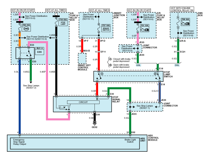
| Circuit Diagram - ABS (2) |

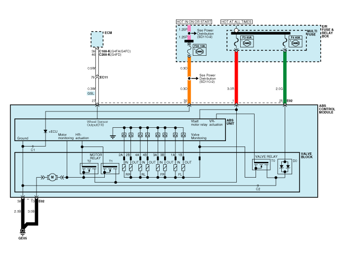
| Circuit Diagram - ABS (3) |

ECU Connector Input/Output (ABS)

|
Wire No. |
Designation |
Current |
max.permissible wire resistance R_L (mΩ) |
|
|
max |
min |
|||
|
13 |
Ground for recirculation pump |
39 A |
10 A |
- |
|
38 |
Ground for solenoid valves and ECU |
15 A |
2 A |
- |
|
1 |
Voltage supply for pump motor |
39 A |
10 A |
- |
|
25 |
Voltage supply for solenoid valves |
15 A |
2 A |
- |
|
32 |
Voltage for hybrid ECU |
1 A |
500 mA |
60 |
|
22,6,20,31 |
signal wheel speed sensor FL, FR, RL,RR |
16.8 mA |
5.9 mA |
250 |
|
34,18,33,19 |
Voltage supply for the active wheel speed sensor FL,FR, RL, RR |
16.8 mA |
5.9 mA |
250 |
|
30 |
Brake light switch (Signal) |
10 mA |
5 mA |
250 |
|
14 |
CAN Low |
30 mA |
20 mA |
250 |
|
26 |
CAN High |
30 mA |
20 mA |
250 |
|
27 |
Wheel speed sensor output |
Open Drain |
- |
- |
ABS Hecu Connector
|
Connector terminal |
Specification |
Condition |
|
|
Number |
Description |
||
|
13 |
Ground for recirculation pump |
Current range: Min.10A Max. 39A |
Always |
|
38 |
Ground for solenoid valves and ECU |
Current range: Min.2A Max. 15A |
Always |
|
1 |
Voltage supply for pump motor |
Battery voltage |
Always |
|
25 |
Voltage supply for solenoid valves |
||
|
34 |
Voltage supply for the active wheel speed sensor FL,FR, RL, RR |
Battery voltage |
IG On |
|
18 |
|||
|
33 |
|||
|
19 |
|||
|
22 |
signal wheel speed sensor FL, FR, RL,RR |
Voltage(High) : 0.26 ~ 0.37 V Voltage (Low) : 0.13 ~ 0.18 V |
On driving |
|
6 |
|||
|
20 |
|||
|
31 |
|||
|
32 |
Voltage for hybrid ECU |
Battery voltage |
KEY ON/OFF |
|
30 |
Brake light switch |
Voltage (High) ≥ 4.5 * IG ON Voltage (Low) ≤ 2.0 * IG ON |
Brake On/Off |
Sensor Output On GDS(ABS)
|
|
Description |
Abbreviation |
Unit |
Remarks |
|
1 |
Vehicle speed sensor |
VEH. SPD |
Km/h |
|
|
2 |
Battery voltage |
BATT. VOL |
V |
|
|
3 |
FL Wheel speed sensor |
FL WHEEL |
Km/h |
|
|
4 |
FR Wheel speed sensor |
FR WHEEL |
Km/h |
|
|
5 |
RL Wheel speed sensor |
RL WHEEL |
Km/h |
|
|
6 |
RR Wheel speed sensor |
RR WHEEL |
Km/h |
|
|
7 |
ABS Warning lamp |
ABS LAMP |
- |
|
|
8 |
EBD Warning lamp |
EBD LAMP |
- |
|
|
9 |
Brake Lamp |
B/LAMP |
- |
|
|
10 |
Pump relay state |
PUMP RLY |
- |
|
|
11 |
Valve relay state |
VALVE RLY |
- |
|
|
12 |
Motor |
MOTOR |
- |
|
|
13 |
Front Left valve(IN) |
FL INLET |
- |
|
|
14 |
Front Right valve (IN) |
FR INLET |
- |
|
|
15 |
Rear Left valve (IN) |
RL INLET |
- |
|
|
16 |
Rear Right valve (IN) |
RR INLET |
- |
|
|
17 |
Front Left valve (OUT) |
FL OUTLET |
- |
|
|
18 |
Front Right valve (OUT) |
FR OUTLET |
- |
|
|
19 |
Rear Left valve(OUT) |
RL OUTLET |
- |
|
|
20 |
Rear Right valve (OUT) |
RR OUTLET |
- |
|
 Description and operation
Description
This specification applies to HCU(Hydraulic Control Unit) and ECU(Electronic
Control Unit) of the HECU.(Hydraulic and Electronic Control Unit)
This specification is ...
 Troubleshooting
Standard Flow of Diagnostic Troubleshooting
Notes With Regard To Diagnosis
The phenomena listed in the following table are not abnormal.
Phenomenon
Ex ...
Other information:
Kia Cee'd JD Service Manual: Sub Frame Repair procedures
Replacement
1.
Loosen the wheel nuts slightly.
Raise the vehicle, and make sure it is securely supported.
2.
Remove the front wheel and tire (A) from front hub.
Tightening torque :
88.2 ...
Kia Cee'd JD Owners Manual: Trailer brakes
If your trailer is equipped with a braking
system, make sure it conforms to your
country’s regulations and that it is properly
installed and operating correctly.
If your trailer weight exceeds the maximum
allowed weight without trailer
brakes, then the trailer will also require its
ow ...
© 2017-2025 www.kceed.com

