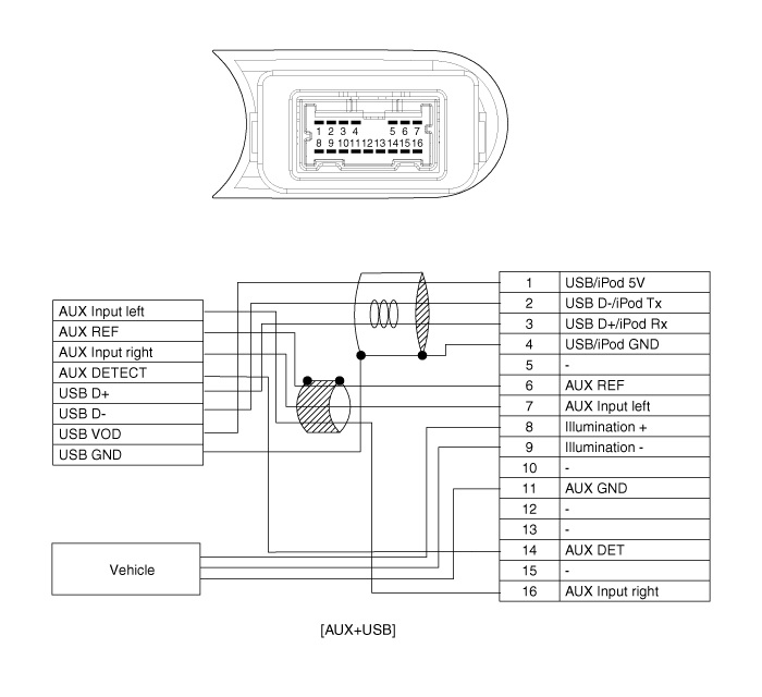
Kia Cee'd: Audio / Multimedia Jack Schematic diagrams
| Circuit Diagram |

|
No |
Terminal Description |
Condition |
Specified Condition |
|
1 |
USB /iPod power |
USB/iPod device is inserted |
4.9V ~ 5.1V |
|
2 |
USB D- |
USB device is inserted |
3.2V ~ 3.45 |
|
3 |
USB D+ |
USB device is inserted |
3.2V ~ 3.45 |
|
4 |
iPod detection line |
iPod device is inserted |
GND |
|
5 |
- |
|
|
|
6 |
AUX Reference Ground |
Always |
Below 1 ohm |
|
7 |
AUX Left Sound Signal |
External Auxiliary device is Audio playing(At time of Aux jack use) |
A waveform synchronized with sound is output |
|
8 |
Illumination (+) |
|
|
|
9 |
Illumination (-) |
|
|
|
10 |
- |
|
|
|
11 |
Multimedia jack ground |
|
GND |
|
12 |
- |
|
|
|
13 |
- |
|
|
|
14 |
AUX Signal Input Detect |
Auxiliary device is inserted |
0V(Low) → 5V(High) |
|
15 |
- |
|
- |
|
16 |
AUX Right Sound Signal |
External Auxiliary device is Audio playing(At time of Aux jack use) |
A waveform synchronized with sound is output |
 Audio Remote Control Repair procedures
Inspection
Type A
1.
Check the audio remote control switch (A) for resistance between terminals
in each switch position.
[Audio]
...
 Multimedia Jack Description and operation
Description
The multimedia jack on the console upper cover is for customers who like to
listen to external portable music players like the MP3, iPod and etc., through
the vehicle ...
Other information:
Kia Cee'd JD Service Manual: Emergency Call (eCall) Unit Repair procedures
Removal
Carry out the Test Mode in the following cases.
–
Replacing the eCall unit
–
Replacing the Back-up Battery (BUB)
...
Kia Cee'd JD Owners Manual: Tilting the sunroof
When the sunshade is closed
If you push the sunroof control lever
upward, the sunshade will slide all the
way open then the sunroof glass will tilt.
To stop the sunroof movement at any
point, pull or push the sunroof control
lever momentarily.
When the sunshade is opened
If you push th ...
© 2017-2026 www.kceed.com

