Kia Cee'd: Ignition Lock Switch / Repair procedures
Signal Circuit Inspection
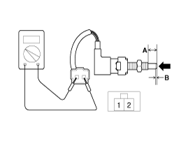
| 1. |
Check ignition lock switch pull-up voltage
| (1) |
IG KEY "OFF", ENGINE "OFF".
|
| (2) |
Disconnect ignition lock switch connector.
|
| (4) |
Measure the voltage between signal terminal of ignition lock
switch harness connector and chassis ground.
|
Specification : 11.5V ~ 13.0V
|
|
|
| 2. |
Check open in ignition lock switch signal circuit
| (1) |
IG KEY "OFF", ENGINE "OFF".
|
| (2) |
Disconnect ignition lock switch connector and ECM connector.
|
| (3) |
Check continuity between signal terminal of lock switch signal
harness connector and ECM harness connector.
|
Specification : Continuity ( below 1.0Ω )
|
|
|
Ground Circuit inspection
| 1. |
IG KEY "OFF", ENGINE "OFF".
|
| 2. |
Disconnect ignition lock switch connector.
|
| 3. |
Check continuity between lock switch signal connector terminal 1 and
chassis ground.
|
Specification : Continuity ( below 1.0Ω )
|
|
Component Inspection
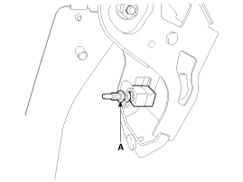
| 1. |
Remove the ignition lock switch.
|
| 2. |
Push the ignition lock switch in the direction of the arrow to make
sure that continuity between terminals. (refer to the table below)
|
Standard value :
Full stroke (A): 12.0 ± 0.3mm (0.4724 ± 0.0118 in.)
ON-OFF point (B): 2.0 mm(0.0787 in.)
|
|
Condition
|
Clutch Pedal pressed
|
Clutch Pedal Released
|
Switch Operation
|
ON (below 1.0Ω )
|
OFF ( Infinite Ω )
|
|
|
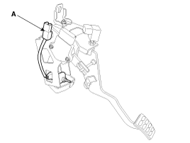
| 1. |
Turn ignition switch OFF and disconnect the negative (-) battery cable.
|
| 2. |
Disconnect ignition lock switch connector (A).
|
| 3. |
Remove the ignition lock switch by loosening a nut (A).
|
| 1. |
Install in the reverse order of removal.
|
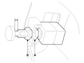
| 2. |
Adjust the ignition switch.
| (1) |
In state of full stroke, adjust the gab by rotating the adjust
nut (A) to satisfy the standard gap range.
|
Standard gap range :
Gasoline : 3 ~ 4 mm (0.1181 ~ 0.1575 in.)
Diesel : 1 ~ 2 mm (0.0394 ~ 0.0787 in.)
|
|
| (2) |
Tighten the nut (B) with the specified torque.
|
Tightening torque:
7.8 ~ 9.8 N (0.8 ~ 1.0 kgf.m, 5.8 ~ 7.2 lb-ft)
|
|
|
Specifications
Item
Specifications
Working voltage
DC
12V
Operating force
14.7 ± ...
Components
1. Master cylinder
2. Ignition lock switch
3. Clutch switch
4. Pedal pad
...

 Specifications
 Clutch Pedal Components and components location