Kia Cee'd: Brake System / Brake Booster Repair procedures
| Brake Booster Operating Test |
For simple checking of the brake booster operation, carry out the following
tests.
| 1. |
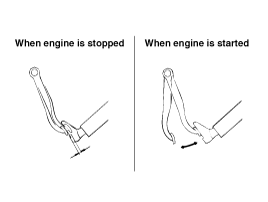
Run the engine for one or two minutes, and then stop it. If the pedal
depresses fully the first time but gradually becomes higher when depressed
succeeding times, the booster is operating properly, if the pedal height
remains unchanged, the booster is inoperative.
|
| 2. |
With the engine stopped, step on the brake pedal several times.
Then step on the brake pedal and start the engine. If the pedal moves
downward slightly, the booster is in good condition. If there is no
change, the booster is inoperative.
|
| 3. |
With the engine running, step on the brake pedal and then stop the engine.Hold
the pedal depressed for 30 seconds. If the pedal height does not change,
the booster is in good condition, if the pedal rises, the booster is
inoperative.
If the above three tests are okay, the booster performance can be determined
as good.
Even if one of the above three tests is not okay, check the check valve,
vacuum hose and booster for malfunction.
|
| Removal [LHD] |
| 1. |
Turn ignition switch OFF and disconnect the negative (-) battery cable.
|
| 2. |
Remove the battery.
(Refer to Engine Electrical system-"Battery")
|
| 3. |
Remove the ECM.
(Refer to Engine control / Fuel System -"Engine Control Module")
|
| 4. |
Remove the master cylinder.
(Refer to Master Cylinder)
|
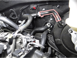
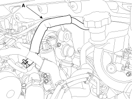
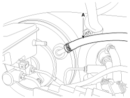
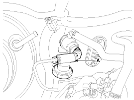
| 5. |
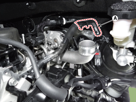
Disconnect the vacuum hose (A) from the brake booster.
[Kappa 1.0 T-GDI]
[Kappa 1.4 MPI]
[Gamma 1.6 MPI ]
[Gamma 1.6 GDI ]
[Gamma 1.6 T-GDI ]
[U-ll 1.4 / 1.6 TCI ]
|
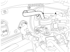
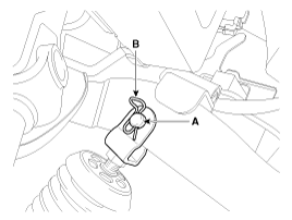
| 6. |
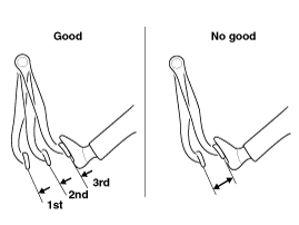
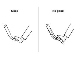
Remove the snap pin (A) and clevis pin (B).
|
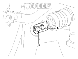
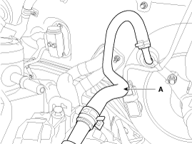
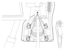
| 7. |
Remove the mounting nuts (A).
|
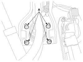
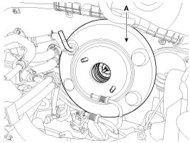
| 8. |
Remove the brake booster (A).
|
| Removal [RHD] |
| 1. |
Turn ignition switch OFF and disconnect the negative (-) battery cable.
|
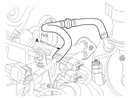
| 2. |
Disconnect the vacuum hose (A) from the brake booster.
|
| 3. |
Remove the master cylinder.
(Refer to Master cylinder)
|
| 4. |
Remove the snap pin (A) and clevis pin (B).
|
| 5. |
Remove the mounting nuts (A).
|
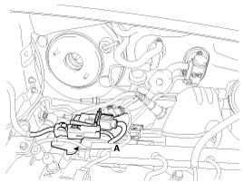
| 6. |
Remove the connector bracket (A).
|
| 7. |
Remove the clutch regulator assembly (A). [MT only]
|
| 8. |
Install the jack to the edge of oil pan to support the engine.
|

| 9. |
Remove the engine mounting support bracket.
(Refer to Engine Mechanical System – “Engine mounting”)
|
| 10. |
Slowly lower the jack and make space to remove the brake booster.
|
| 11. |
Remove the brake booster.
|
| Inspection |
| 1. |
Inspect the check valve in the vacuum hose.
|

| 2. |
Check the boot for damage.
|
| Installation |
| 1. |
Install in the reverse order of removal.
|
| 2. |
After installing, bleed the brake system.
(Refer to Brake system bleeding)
|
| 3. |
After be equipped perform bleeding air procedure in clutch release cylinder
after pouring the brake fluid. [MT only]
(Refer to Clutch - "Clutch Release Cylinder")
|
 Brake Booster Components and components location
Components [LHD]
1. Brake booster
2. Master cylinder assembly
3. O-ring
Components [RHD]
1. Brake booster
...
 Vacuum Pump Components and components location
Components
Gamma 1.6 T-GDI
1. Vacuum pump
2. Bracket
3. Lead wire assembly
Kappa 1.0 T-GDI
1. Cylinder head
...
Other information:
Kia Cee'd JD Service Manual: Injector Troubleshooting
Signal Waveform
The three waveforms below are taken from the #1 and #4 injectors. The top waveform
is from the high side (feed side) of the #1 and #4 injectors, while the middle
waveform is from the low side (ground side) of the #1 injector and the bottom
waveform is from th ...
Kia Cee'd JD Service Manual: Engine Cover Repair procedures
Removal and Installation
1.
Remove the engine cover (A).
2.
Install in the reverse order of removal.
...
© 2017-2026 www.kceed.com
