Kia Cee'd: Front Axle Assembly / Front Hub / Knuckle / Repair procedures
Kia Cee'd JD Service Manual / Driveshaft and axle / Front Axle Assembly / Front Hub / Knuckle / Repair procedures
| Replacement |
| 1. |
Loosen the wheel nuts slightly.
Raise the vehicle, and make sure it is securely supported.
|
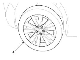
| 2. |
Remove the front wheel and tire (A) from front hub .
|

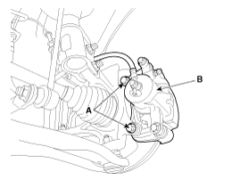
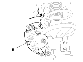
| 3. |
Remove the brake caliper mounting bolts (A), and then place the brake
caliper assembly (B) with wire.
|
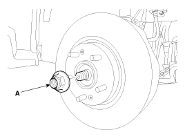
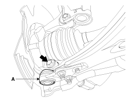
| 4. |
Remove driveshaft caulking nut (A) from the front hub under applying
the brake.
|
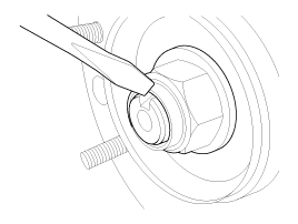
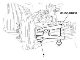
| 5. |
Remove the tie rod end ball joint (C) from the knuckle by using the
SST (09568-34000).
|
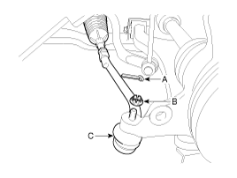
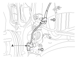
| 6. |
Remove the wheel speed sensor(A).
|
| 7. |
Remove the lower arm (A) from the knuckle.
|
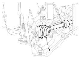
| 8. |
Disconnect the driveshaft (A) from the front hub assembly.
|
| 9. |
Loosen the knuckle upper mounting bolts and then remove the knuckle
assembly (A).
|
| Disassembly |
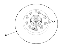
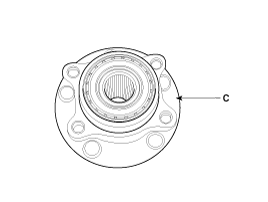
| 1. |
Loosen the mounting screws (A-2ea) and then remove the brake disc (B)
from the hub.
|
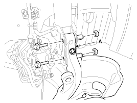
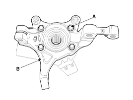
| 2. |
Loosen the bolts (A-4ea) and then remove the knuckle (B) from the hub
(C).
|
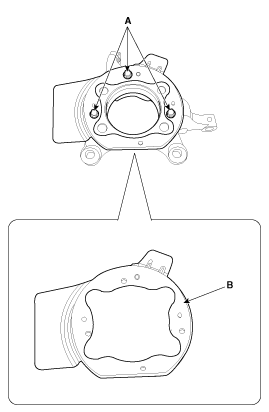
| 3. |
Loosen the bolts (A-3ea) and then remove the dust cover (B) from the
knuckle.
|
| 4. |
Reassembly in the reverse order of disassembly.
|
| Inspection |
| 1. |
Check the hub for cracks and the splines for wear.
|
| 2. |
Check the knuckle for cracks.
|
| 3. |
Check the bearing for cracks or damage.
|
| 4. |
Pad surface of brake assembly and sliding surface of brake disc must
be free from grease, oil, rust and other foreign substances.
|
| Installation |
| 1. |
Install in the reverse order of removal.
|

 Components and components location
Components
1. Tire
2. Drive shaft coking nut
3. Brake disc
4. Dust cover
5. Wheel hub assembly
6. Knuckle
...

Other information:
: Front Seats
Front Seat Precautions
WARNING: Sitting improperly, out
of position or with the seatback reclined
too far can take weight off the seat
cushion and affect the decision of the
passenger sensing system, resulting in
serious injury or death in the event of a
crash. Always sit upright against your ...
Kia Cee'd JD Service Manual: Front Fog Lamps Repair procedures
Inspection
1.
Disconnect the negative (-) battery terminal.
2.
Remove the lighting switch of the multifunction switch.
(Refer to Multifunction Switch)
3.
With the front fog lamp switch, make sure ...
© 2017-2026 www.kceed.com
