Kia Cee'd: Parking Brake System / Electronic Parking Brake (EPB) Schematic diagrams
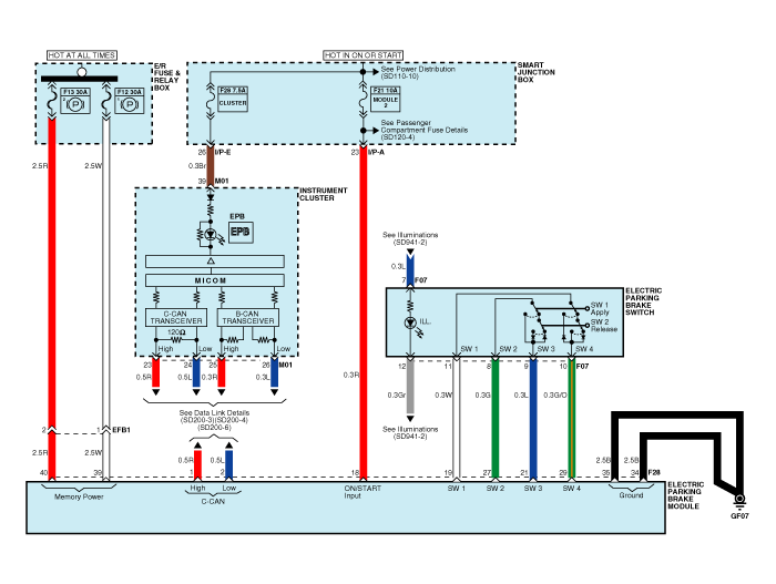
| EPB Circuit Diagram (1) |
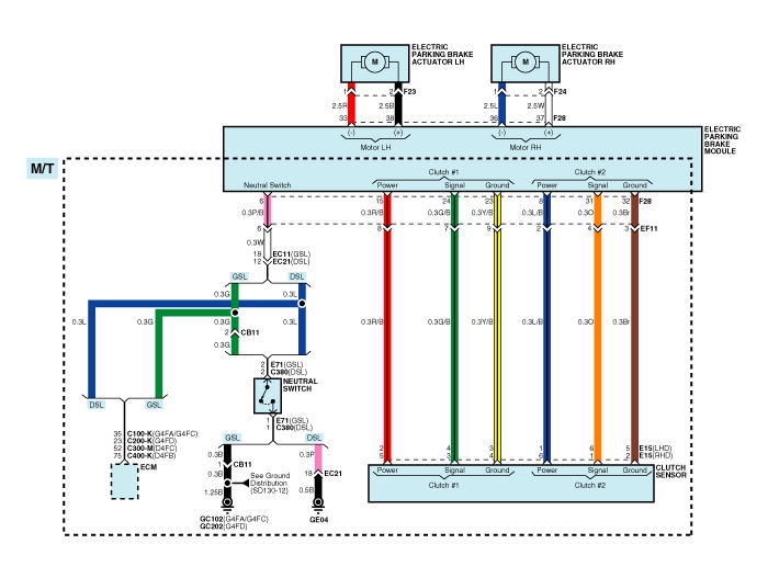
| EPB Circuit Diagram (2) |
| EPB connector input/output |

|
Pin No. |
Function |
Pin No. |
Function |
|
1 |
CAN_High |
21 |
EPB switch 3 |
|
2 |
CAN_Low |
22 |
- |
|
3 |
- |
23 |
Clutch ground 1 (MT only) |
|
4 |
- |
24 |
Output signal 1 (MT only) |
|
5 |
- |
25 |
- |
|
6 |
Neutral switch (MT only) |
26 |
- |
|
7 |
- |
27 |
EPB switch 2 |
|
8 |
Clutch power 2 |
28 |
- |
|
9 |
- |
29 |
EPB switch 4 |
|
10 |
- |
30 |
- |
|
11 |
- |
31 |
Output signal 2 (MT only) |
|
12 |
- |
32 |
Clutch ground 2 (MT only) |
|
13 |
- |
33 |
Rear left caliper motor - |
|
14 |
- |
34 |
Ground |
|
15 |
Clutch power 1 (MT only) |
35 |
Ground |
|
16 |
- |
36 |
Rear right caliper motor - |
|
17 |
- |
37 |
Rear right caliper motor + |
|
18 |
Ignition 1 |
38 |
Rear left caliper motor + |
|
19 |
EPB switch 1 |
39 |
Rear right motor power |
|
20 |
- |
40 |
Rear left motor power |
 Electronic Parking Brake (EPB) Description and operation
Description
The EPB is an electronic parking brake.
The EPB is different from existing parking systems which operated with the brake
pedal or the lever type. The EPB system se ...
 Electronic Parking Brake (EPB) Repair procedures
Removal
1.
Turn ignition OFF and disconnect the negative (-) battery cable.
2.
Remove the floor console assembly.
(Refer to ...
Other information:
: Interior Lamp Function. Adjusting the Instrument Panel Lighting Brightness.
Ambient Lighting
Interior Lamp Function
What Is the Interior Lamp Function
The interior lamp function switches the
courtesy and door lamps on or off.
Switching the Interior Lamp Function On and Off
Set the switch to the middle position.
Adjusting the Instrument Panel Lighting Brightness
The instrument lighting dim ...
Kia Cee'd JD Owners Manual: Storage compartment
CAUTION
To avoid possible theft, do not
leave valuables in the storage
compartment.
Always keep the storage compartment
covers closed while
driving. Do not attempt to place
so many items in the storage
compartment that the storage
compartment cover can not close
securel ...
