Kia Cee'd: Engine Control System / Accelerator Position Sensor (APS) Repair procedures
Kia Cee'd JD Service Manual / Fuel System / Engine Control System / Accelerator Position Sensor (APS) Repair procedures
| Inspection |
| 1. |
Connect the GDS on the Data Link Connector (DLC).
|
| 2. |
Turn the ignition switch ON.
|
| 3. |
Measure the output voltage of the APS 1 and 2 at C.T and W.O.T.
|
| Removal |
| 1. |
Turn the ignition switch OFF and disconnect the negative (-) battery
cable.
|
| 2. |
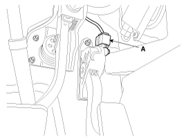
Disconnect the accelerator position sensor connector (A).
|
| 3. |
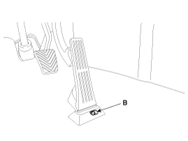
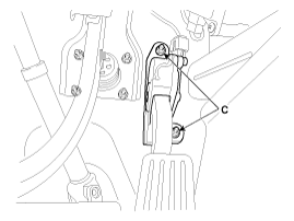
Remove the installation bolt (B) and nuts (C), and then remove the accelerator
pedal module.
|
| Installation |
| 1. |
Installation is reverse of removal.
|
 Accelerator Position Sensor (APS) Schematic diagrams
Circuit Diagram
...
 Injector Description and operation
Description
The GDI injector is similar to a standard injector, but sprays fuel at a much
higher pressure directly into the combustion chamber and has a swirl disc to
get the fue ...
Other information:
Kia Cee'd JD Service Manual: Movable Glass Repair procedures
Replacement
1.
Open the movable glass fully.
2.
Loosen the movable glass mounting screws (A).
•
...
Kia Cee'd JD Owners Manual: Speedometer
■ Type A
■ Type B • km/h
■ Type B • MPH
■ Type C • km/h
■ Type C • MPH
The speedometer indicates the vehicle
speed.
The speedometer is calibrated in kilometers
per hour and/or miles per hour. ...
© 2017-2026 www.kceed.com


