
Kia Cee'd: Engine Control System / ISG (Idle Stop & Go) Schematic diagrams
Kia Cee'd JD Service Manual / Fuel System / Engine Control System / ISG (Idle Stop & Go) Schematic diagrams
| Schematic Diagram |
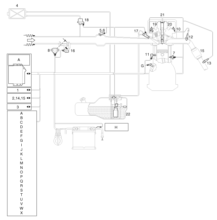
| 1. C-CAN
High/Low 2. MIL. Lamp 3. Immobilizer 4. Canister 5. Manifold Absolute Pressure Sensor (MAPS) 6. Intake Air Temperature Sensor (IATS) 7. Engine Coolant Temperature Sensor (ECTS) 8. Throttle Position Sensor (TPS) [integrated into ETC Module] 9. Camshaft Position Sensor (CMPS) [Bank 1 / Intake] 10. Camshaft Position Sensor (CMPS) [Bank 1 / Exhaust] 11. Knock Sensor (KS) 12. Heated Oxygen Sensor (HO2S) [Bank 1 / Sensor 1] 13. Heated Oxygen Sensor (HO2S) [Bank 1 / Sensor 2] 14. Accelerator Position Sensor (APS) 15. A/C Pressure Transducer (APT) 16. ETC Motor [integrated into ETC Module] 17. Injector 18. Purge Control Solenoid Valve (PCSV) 19. CVVT Oil Control Valve (OCV) [Bank 1 / Intake] 20. CVVT Oil Control Valve (OCV) [Bank 1 / Exhaust] 21. Ignition Coil 22. Fuel pump Motor |
A. Cluster
B. Clutch switch C. Neutral switch D. Brake booster vacuum pressure sensor (BBVPS) E. Alternator F. Start motor G. Crankshaft Position Sensor (CKPS) H. Battery sensor I. Hood switch J. Door switch (Driver's) K. Seat belt switch (Driver's) L. DC/DC converter M. Audio N. A/C Control module O. A/C Switch P. Defroster switch Q. A/C Compressor R. Blower motor S. Blower relay T. Evaporator sensor U. Ambient temperature sensor V. Blower resistor [Manual A/C] W. FET (Field Effect Transistor) [Auto A/C] X. Catalytic convertor |
The ISG system is strongly networked with the power management. In the
event of battery replacement, disconnection of the battery terminal
or after changing the engine management system, the reference data regarding
the battery charge state and battery condition can be lost.
They are only available again a closed-circuit current measurement of
approximate 4 hours in which the vehicle may not be wakened. In this
time, the ISG system is inactive.
|

 ISG (Idle Stop & Go) Repair procedures
Inspection
1.
Remove the ISG switch from the switch assembly.
2.
Check the continuity between the switch 3 and 6 terminals as the ISG
...

Other information:
: Locating the Brake Fluid Reservoir. Checking the Brake Fluid.
Locating the Brake Fluid Reservoir
See Under Hood Overview.
Checking the Brake Fluid
WARNING: Do not use any fluid
other than the recommended brake fluid
as this will reduce brake efficiency. Use
of incorrect fluid could result in the loss
of vehicle control, serious personal injury
or death.
W ...
Kia Cee'd JD Service Manual: General safety information and caution
Precautions
General Precautions
Please read the following precautions carefully before performing the airbag
system service.
Observe the instructions described in this manual, or the airbags could accidentally
deploy and cause damage or injuries.
• ...
© 2017-2026 www.kceed.com
