
Kia Cee'd: Dual Clutch Transmission Control System / Inhibitor Switch Repair procedures
| Inspection |
| 1. |
Inspect for loosened connectors, faulty connections, bends, corrosion,
contamination, deformation, or damage.
|
| 2. |
Disconnect the inhibitor switch connector.
|
| 3. |
Check the voltage on the power supply terminal and the ground of the
inhibitor switch wiring.
|
| 4. |
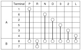
Use the following signal code chart to check the electric current flow
for each terminal in each gear.
|
| Removal |
| 1. |
Remove the air cleaner assembly and air duct.
(Refer to Engine Mechanical System - "Air cleaner")
|

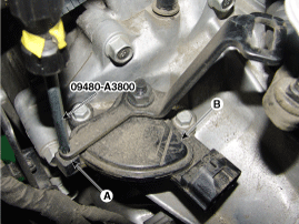
| 2. |
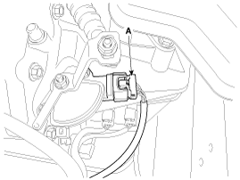
Disconnect the inhibitor switch connector (A).
|
| 3. |
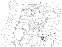
Remove the shift cable mounting nut (A).
|
| 4. |
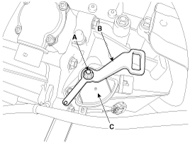
Loosen the nut (A), and then remove the manual lever (B).
|
| 5. |
Loosen the mounting bolt, and then remove the inhibitor switch (C).
|
| Installation |
| 1. |
Install in the reverse order of removal.
|
 Inhibitor Switch Schematic diagrams
Schematic Diagrams
...
 Shift Lever Components and components location
Components
1. Shift lever assembly
2. Shift cable assembly
3. Retainer
4. Bolt
5. Nut
6. Manual control lever
...
Other information:
: Using the Instrument Cluster Display Controls
WARNING: Driving while distracted
can result in loss of vehicle control, crash
and injury. We strongly recommend that
you use extreme caution when using any
device that may take your focus off the
road. Your primary responsibility is the
safe operation of your vehicle. We
recommend against th ...
: Blind Spot Information System Requirements. Switching Blind Spot Information System On and Off
Blind Spot Information System Requirements
Blind spot information system turns on
when all the following occur:
You start your vehicle.
You shift into drive (D).
The vehicle speed is greater than
6 mph (10 km/h).
Switching Blind Spot Information System On and Off
To switch blind spot informa ...
