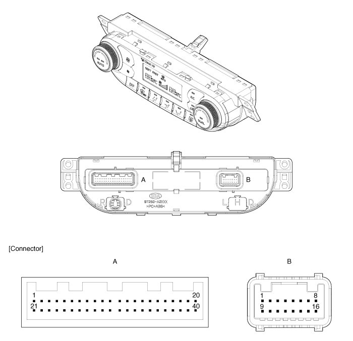
Kia Cee'd: Controller / Heater & A/C Control Unit (DATC) Components and components location
Kia Cee'd JD Service Manual / Heating,Ventilation, Air Conditioning / Controller / Heater & A/C Control Unit (DATC) Components and components location
| Components |

Gasline
Connector Pin Function
|
Connector |
Pin
No. |
Function |
Connector |
Pin
No. |
Function |
|
A |
1 |
Tail Lamp (+) |
A |
29 |
Humidity (PWM) |
|
2 |
Sensor REF (+5V) |
30 |
Photo Sensor (-) - Left |
||
|
3 |
C-CAN (High) |
31 |
- |
||
|
4 |
C-CAN (Low) |
32 |
Photo Sensor (-) - Right |
||
|
5 |
Mode Actuator (Vent) |
33 |
ECV + |
||
|
6 |
Mode Actuator (Defog) |
34 |
ECV - (Ground) |
||
|
7 |
Mode Actuator Feedback |
35 |
Fet (Gate) |
||
|
8 |
Intake Actuator (Fresh) |
36 |
Duct Sensor (+) - Vent |
||
|
9 |
Intake Actuator (Recirculation) |
37 |
Duct Sensor (+) - Floor |
||
|
10 |
Intake Actuator Feedback |
38 |
- |
||
|
11 |
K-Line |
39 |
- |
||
|
12 |
HTD (Rear Defrost Indicator) |
40 |
- |
||
|
13 |
Rear Defog Switch |
B |
1 |
Ground |
|
|
14 |
Temperature Actuator (Cool) - Driver |
2 |
Sensor Ground |
||
|
15 |
Temperature Actuator (Warm) - Driver |
3 |
Fet (Drain Feedback) |
||
|
16 |
Temperature Actuator Feedback - Driver |
4 |
Ionizer Diagnosis |
||
|
17 |
- |
5 |
Clean Signal |
||
|
18 |
- |
6 |
ION Signal |
||
|
19 |
- |
7 |
Ignition 1 |
||
|
20 |
Rheostat (ILL-) |
8 |
Ignition 2 |
||
|
21 |
Detent Out (+) |
9 |
Ground |
||
|
22 |
- |
10 |
- |
||
|
23 |
PTC Relay |
11 |
Temperature Actuator Feedback - Passenger |
||
|
24 |
- |
12 |
Temperature Actuator (Cool) - Passenger |
||
|
25 |
- |
13 |
Temperature Actuator (Warm) - Passenger |
||
|
26 |
- |
14 |
Blower Motor (+) |
||
|
27 |
Ambient Temperature Sensor (+) |
15 |
- |
||
|
28 |
Evaporator Temperature Sensor (+) |
16 |
Battery |
Diesel
Connector Pin Function
|
Connector |
Pin
No. |
Function |
Connector |
Pin
No. |
Function |
|
A |
1 |
Tail Lamp (+) |
A |
29 |
Humidity (PWM) |
|
2 |
Sensor REF (+5V) |
30 |
Photo Sensor (-) - Left |
||
|
3 |
C-CAN (High) |
31 |
- |
||
|
4 |
C-CAN (Low) |
32 |
Photo Sensor (-) - Right |
||
|
5 |
Mode Actuator (Vent) |
33 |
ECV + |
||
|
6 |
Mode Actuator (Defog) |
34 |
ECV - (Ground) |
||
|
7 |
Mode Actuator Feedback |
35 |
Fet (Gate) |
||
|
8 |
Intake Actuator (Fresh) |
36 |
Duct Sensor (+) - Vent |
||
|
9 |
Intake Actuator (Recirculation) |
37 |
Duct Sensor (+) - Floor |
||
|
10 |
Intake Actuator Feedback |
38 |
- |
||
|
11 |
K-Line |
39 |
- |
||
|
12 |
HTD (Rear Defrost Indicator) |
40 |
- |
||
|
13 |
Rear Defog Switch |
B |
1 |
Ground |
|
|
14 |
Temperature Actuator (Cool) - Driver |
2 |
Sensor Ground |
||
|
15 |
Temperature Actuator (Warm) - Driver |
3 |
Fet (Drain Feedback) |
||
|
16 |
Temperature Actuator Feedback - Driver |
4 |
Ionizer Diagnosis |
||
|
17 |
- |
5 |
Clean Signal |
||
|
18 |
- |
6 |
ION Signal |
||
|
19 |
- |
7 |
Ignition 1 |
||
|
20 |
Rheostat (ILL-) |
8 |
Ignition 2 |
||
|
21 |
Detent Out (+) |
9 |
Ground |
||
|
22 |
- |
10 |
- |
||
|
23 |
PTC Relay 2 |
11 |
Temperature Actuator Feedback - Passenger |
||
|
24 |
PTC Relay 3 |
12 |
Temperature Actuator (Cool) - Passenger |
||
|
25 |
PTC ON Signal |
13 |
Temperature Actuator (Warm) - Passenger |
||
|
26 |
- |
14 |
Blower Motor (+) |
||
|
27 |
Ambient Temperature Sensor (+) |
15 |
- |
||
|
28 |
Evaporator Temperature Sensor (+) |
16 |
Battery |
 Heater & A/C Control Unit (MANUAL) Repair procedures
Replacement
•
When prying with a flat-tip screwdriver, wrap it with protective
...
 Heater & A/C Control Unit (DATC) Repair procedures
Self Diagnosis
1.
Self-diagnosis process
2.
How to read self-diagnostic code
After the display the panel blinks three t ...
Other information:
Ford Escape 2020-2026 Owners Manual: Cross Traffic Alert Precautions. Cross Traffic Alert Limitations. Switching Cross Traffic Alert On and Off
Cross Traffic Alert Precautions
WARNING: Do not use the cross
traffic alert system as a replacement for
using the interior and exterior mirrors or
looking over your shoulder before
reversing out of a parking space. The
cross traffic alert system is not a
replacement for careful driving.
WARNIN ...
Kia Cee'd JD Service Manual: Steering Column Shroud Panel Components and components location
Component Location
1. Steering column lower shroud
panel
2. Steering column upper shroud
panel
...
© 2017-2026 www.kceed.com

