Kia Cee'd: Brake System / Brake Pedal Repair procedures
| Removal [LHD] |
| 1. |
Turn ignition switch OFF and disconnect the negative (-) battery cable.
|
| 2. |
Remove the crash pad lower panel.
(Refer to Body - "Crash pad lower panel")
|
| 3. |
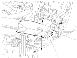
Remove the shower duct (A).
|
| 4. |
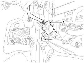
Disconnect the stop lamp switch connector (A).
|
| 5. |
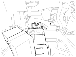
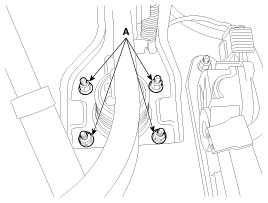
Remove the brake pedal member mounting bolt (A).
|
| 6. |
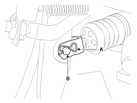
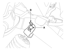
Remove the snap pin (A) and clevis pin (B).
|
| 7. |
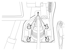
Remove the brake pedal member assembly mounting nuts and then remove
the brake pedal assembly.
|
| Removal [RHD] |
| 1. |
Turn ignition switch OFF and disconnect the negative (-) battery cable.
|
| 2. |
Remove the crash pad lower panel.
(Refer to Body - "Crash pad lower panel")
|
| 3. |
Remove the junction box.
|
| 4. |
Disconnect the stop lamp switch connector (A).
|
| 5. |
Remove the brake pedal member mounting bolt (A).
|
| 6. |
Remove the snap pin (A) and clevis pin (B).
|
| 7. |
Remove the brake pedal member assembly mounting nuts and then remove
the brake pedal assembly.
|
| Inspection |
| 1. |
Check the bushing for wear.
|
| 2. |
Check the brake pedal for bending or twisting.
|
| 3. |
Check the brake pedal return spring for damage.
|
| 4. |
Check the stop lamp switch.
|
| Installation [LHD] |
| 1. |
Pre-tighten the bracket fixing bolt (A) in dash panel.
|
| 2. |
Install the brake booster and brake pedal member fixing nuts (A) securely.
|
| 3. |
Tighten the bolt (A) securely in dash panel.
|
| 4. |
Install the snap pin (A) and clevis pin (B).
|
| 5. |
Install the stop lamp switch securely.
|
| 6. |
Connect the stop lamp switch connector (A).
|
| 7. |
Adjust the brake pedal height and free play.
|
| 8. |
Check the brake pedal operation after installing the brake pedal.
|
| 9. |
Install the shower duct (A).
|
| 10. |
Install the crash pad lower panel.
(Refer to Body - "Crash pad lower panel")
|
| 11. |
Reconnect the battery negative cable.
|
| Installation [RHD] |
| 1. |
Pre-tighten the bracket fixing bolt (A) in dash panel.
|
| 2. |
Install the brake booster and brake pedal member fixing nuts (A) securely.
|
| 3. |
Tighten the bolt (A) securely in dash panel.
|
| 4. |
Install the snap pin (A) and clevis pin (B).
|
| 5. |
Install the stop lamp switch securely.
|
| 6. |
Connect the stop lamp switch connector (A).
|
| 7. |
Adjust the brake pedal height and free play.
|
| 8. |
Check the brake pedal operation after installing the brake pedal.
|
| 9. |
Install the junction box.
(Refer to Body Electrical - "Relay Box")
|
| 10. |
Install the crash pad lower panel.
(Refer to Body - "Crash pad lower panel")
|
| 11. |
Reconnect the battery negative cable.
|
| Adjustment |
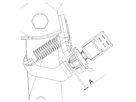
| Stop lamp switch clearance adjustment |
| 1. |
Disconnect the stop lamp switch connector (A).
|
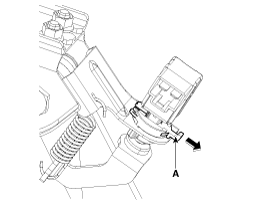
| 2. |
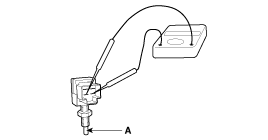
Pull the locking plate (A) as indicated by the arrow.
|
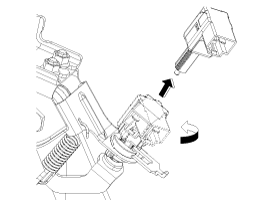
| 3. |
Turn stop lamp switch 45° counterclockwise and remove it.
|
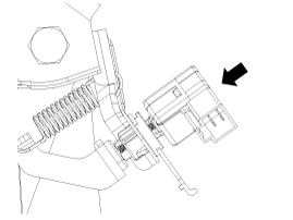
| 4. |
Fix the brake pedal arm and insert fully the stop lamp switch as hiding
contact part.
|
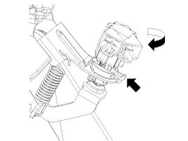
| 5. |
After inserting, turn the stop switch (A) 45° clockwise, and then assemble
locking plate (B) by pushing.
|
| 6. |
Confirm the gap between stop lamp switch and bracket.
|
| 7. |
Connect the stop lamp switch connector.
|
 Brake Pedal Components and components location
Components [LHD]
1. Cowl bracket
2. Brake pedal member assembly
3. Stop lamp switch
4. Return spring
5. Brake pedal
6. Bolt
...
 Front Disc Brake Components and components location
Components
1. Guide rod bolt
2. Bleed screw
3. Caliper carrier
4. Caliper body
5. Inner pad shim
6. Brake pad
7. Pad retainer
8. Retur ...
Other information:
Kia Cee'd JD Owners Manual: AUTO (Automatic) control
The rain sensor located on the upper end
of the windshield glass senses the
amount of rainfall and controls the wiping
cycle for the proper interval. The more it
rains, the faster the wiper operates.When
the rain stops, the wiper stops.
To vary the speed setting, turn the speed
contro ...
Kia Cee'd JD Owners Manual: Changing tires
1. Park on a level surface and apply
the parking brake firmly.
2. Shift the shift lever into R
(Reverse) with manual transaxle
or P (Park) with automatic
transaxle.
3. Activate the hazard warning flasher.
4. Remove the wheel lug nut wrench,
jack, jack handle, and spare tire
from t ...

