Kia Cee'd: ABS(Anti-Lock Brake System) / Troubleshooting
|
Phenomenon |
Explanation |
||||||
|
System check sound |
When starting the engine, a thudding sound can sometimes be heard coming
from inside the engine compartment. This is because the system operation check is being performed. |
||||||
|
ABS operation sound |
|
||||||
|
ABS operation (Long braking distance) |
For road surfaces such as snow-covered and gravel roads, the braking distance
for vehicles with ABS can sometimes be longer than that for other vehicles.
Accordingly, advise the customer to drive safely on such roads by lowering
the vehicle speed. |
||||||
|
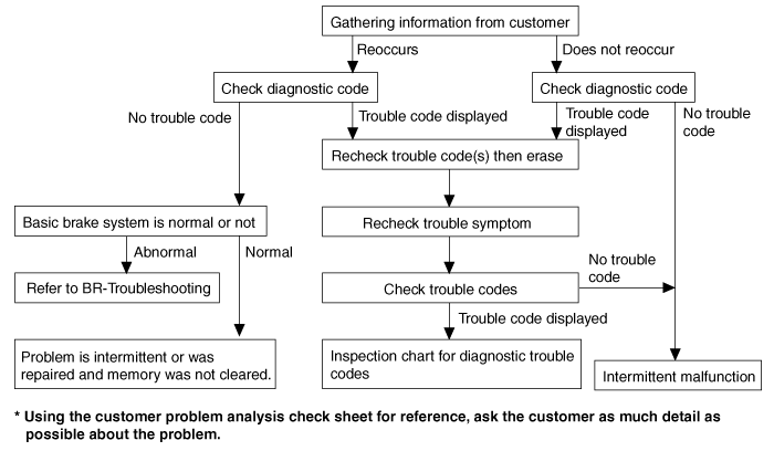
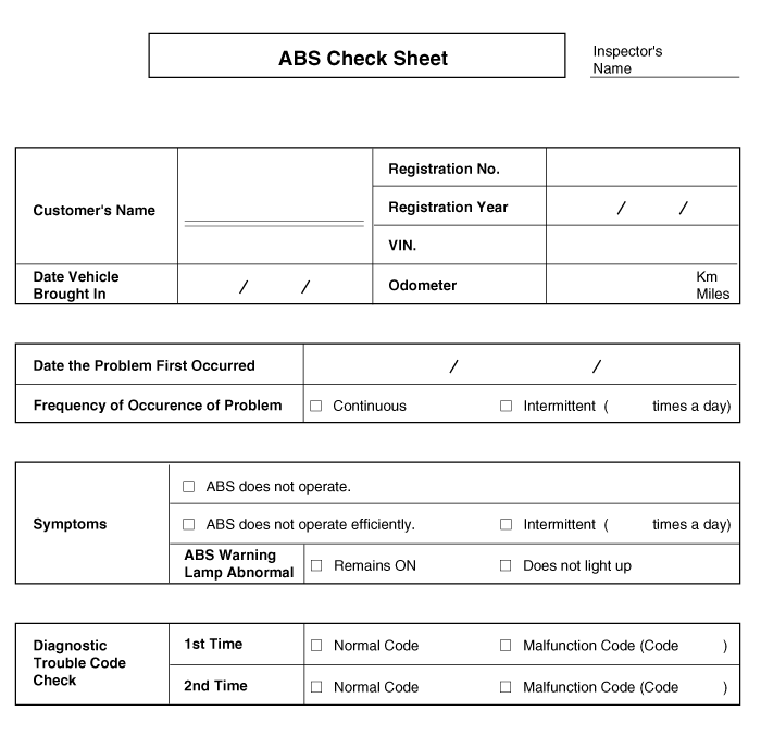
Diagnosis detection conditions can vary depending on the diagnosis code.
When checking the trouble symptom after the diagnosis code has been erased, ensure that the requirements listed in "Comment" are met. |
|||||||
|
Symptom |
Suspect Area |
||||||||
|
ABS does not operate. |
Only when 1. ~ 4. are all normal and the problem is still occurring, replace
the HECU.
|
||||||||
|
ABS does not operate intermittently. |
Only when 1. ~ 4. are all normal and the problem is still occurring, replace
the ABS actuator assembly.
|
||||||||
|
Communication with GDS is not possible. (Communication with any system is not possible) |
|
||||||||
|
Communication with GDS is not possible. (Communication with ABS only is not possible) |
|
||||||||
|
When ignition key is turned ON (engine OFF), the ABS warning lamp does not light up. |
|
||||||||
|
Even after the engine is started, the ABS warning lamp remains ON. |
|
During ABS operation, the brake pedal may vibrate or may not be able
to be depressed. Such phenomena are due to intermittent changes in hydraulic
pressure inside the brake line to prevent the wheels from locking and
is not an abnormality.
|


|
Trouble Symptoms |
Possible Cause |
||||||||
|
Brake operation varies depending on driving conditions and road surface
conditions, so diagnosis can be difficult. However if a normal DTC is displayed,
check the following probable cause. When the problem is still occurring,
replace the ABS control module. |
|
| 1. |
Connect the GDS with the data link connector and turn the ignition switch
ON.
|
| 2. |
Verify that the DTC code is output.
Is the DTC code output?
|
|
|
▶ Check the power source circuit.
|
|
|
▶ Erase the DTC and recheck using
GDS. |


| 1. |
Disconnect the connector from the ABS control module.
|
| 2. |
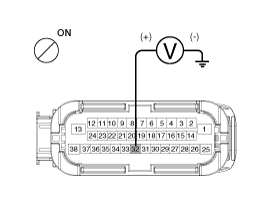
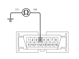
Turn the ignition switch ON, measure the voltage between terminal 32
of the ABS control module harness side connector and body ground.
Is the voltage within specification?
|
|
|
▶ Check the ground circuit.
|
|
|
▶ Check the harness or connector
between the fuse (10A) in the engine compartment junction block and the
ABS control module. Repair if necessary. |
| 1. |
Disconnect the connector from the ABS control module.
|
| 2. |
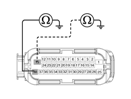
Check for continuity between terminals 13, 38 of the ABS control module
harness side connector and ground point.
Is there continuity?
|
|
|
▶ Check the wheel speed sensor
circuit. |
|
|
▶ Repair an open in the wire
and ground point. |
| 1. |
Inspect the wheel speed sensor circuit. (Refer to the DTC troubleshooting
procedures)
Is it normal?
|
|
|
▶ Check the hydraulic circuit
for leakage. |
|
|
▶ Repair or replace the wheel
speed sensor. |
| 1. |
Inspect leakage of the hydraulic lines.
Is it normal?
|
|
|
▶ The problem is still occurring,
replace the ABS control module. |
|
|
▶ Repair the hydraulic lines
for leakage. |

|
Trouble Symptoms |
Possible Cause |
||||||||
|
Brake operation varies depending on driving conditions and road surface
conditions, so diagnosis can be difficult. However if a normal DTC is displayed,
check the following probable cause. When the problem is still occurring,
replace the ABS control module. |
|
| 1. |
Connect the GDS with the data link connector and turn the ignition switch
ON.
|
| 2. |
Verify that the DTC code is output.
Is the DTC code output?
|
|
|
▶ Check the wheel speed sensor
circuit. |
|
|
▶ Erase the DTC and recheck using
GDS. |
| 1. |
Refer to the DTC troubleshooting procedures.
Is it normal?
|
|
|
▶ Check the stop lamp switch
circuit. |
|
|
▶ Repair or replace the wheel
speed sensor. |
| 1. |
Inspection leakage of the hydraulic lines.
Is it normal?
|
|
|
▶ The problem is still occurring,
replace the ABS control module. |
|
|
▶ Repair the hydraulic lines
for leakage. |

|
Trouble Symptoms |
Possible Cause |
||||||
|
Possible defect in the power supply system (including ground) for the diagnosis
line. |
|
| 1. |
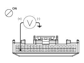
Measure the voltage between terminal 16 of the data link connector and
body ground.
Is voltage within specification?
|
|
|
▶ Check the ground circuit for
the diagnosis. |
|
|
▶ Repair an open in the wire.
Check and replace fuse (15A) from the engine compartment junction block.
|

| 1. |
Check for continuity between terminal 4 of the data link connector and
body ground.
Is there continuity?
|
|
|
▶ Repair an open in the wire
between terminal 4 of the data link connector and ground point. |

|
Trouble Symptoms |
Possible Cause |
||||||
|
When communication with GDS is not possible, the cause may be probably an
open in the HECU power circuit or an open in the diagnosis output circuit.
|
|
| 1. |
Disconnect the connector from the ABS control module.
|
| 2. |
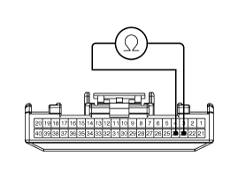
Check for continuity between terminals 26, 14 of the ABS control module
connector and 6, 14 of the data link connector.
Is there continuity?
|
|
|
▶ Check the power source of ABS
control module. |
|
|
▶ Repair an open in the wire.
|
| 1. |
Disconnect the connector from the ABS control module.
|
| 2. |
Turn the ignition switch ON, measure the voltage between terminal 32
of the ABS control module harness side connector and body ground.
Is voltage within specification?
|
|
|
▶ Check for poor ground. |
|
|
▶ Check the harness or connector
between the fuse (10A) in the engine compartment junction block and the
ABS control module.Repair if necessary. |
| 1. |
Check for continuity between terminal 4 of the data link connector and
ground point.
|

|
Trouble Symptoms |
Possible Cause |
||||||||
|
When current flows in the HECU the ABS warning lamp turns from ON to OFF as the initial check. Therefore if the lamp does not light up, the cause may be an open in the lamp power supply circuit, a blown bulb, an open in the both circuits between the ABS warning lamp and the HECU, and the faulty HECU. |
|
| 1. |
Disconnect the connector from the ABS control module and turn the ignition
switch ON.
|
| 2. |
Does the ABS warning lamp light up?
|
| 1. |
Disconnect the instrument cluster connector (M01) and turn the ignition
switch ON.
|
| 2. |
Measure the voltage between terminal (M01) 39 of the cluster harness
side connector and body ground.
Is voltage within specification?
|
|
|
▶ Check the CAN circuit resistance
for ABS warning lamp. |
|
|
▶ Check for blown fuse. |
| 1. |
Disconnect the instrument cluster connector (M01) and turn the ignition
switch OFF.
|
| 2. |
Measure the resistance between terminal (M01) 23 and 24 of the cluster
harness side connector.
|
|
|
▶ Repair ABS warning lamp
bulb or instrument cluster assembly. |
|
|
▶ Check the CAN circuit
wiring for ABS warning lamp. |
| 1. |
Disconnect the instrument cluster connector (M01) and ABS HECU connector,
and then turn the ignition switch OFF.
|
| 2. |
Check for continuity between terminal (M01) 23 of the cluster harness
side connector and terminal 26 of ABS HECU harness side.
Check for continuity between terminal (M01) 24 of the cluster harness
side connector and terminal 14 of ABS HECU harness side.
Is resistance within specification?
|
|
|
▶ Repair short of wiring
between terminal 26, 14 of ABS HECU harness connector and ABS warning lamp
module. |
|
|
▶ Repair open of wiring
between terminal 26, 14 of ABS HECU harness connector and ABS warning lamp
module. |

|
Trouble Symptoms |
Possible Cause |
||||||||
|
If the HECU detects trouble, it lights the ABS warning lamp while at the
same time prohibiting ABS control. At this time, the HECU records a DTC in memory. Even though the normal code is output, the ABS warning lamp remains ON, then the cause may be probably an open or short in the ABS warning lamp circuit. |
|
| 1. |
Connect the GDS to the 16P data link connector located behind the driver's
side kick panel.
|
| 2. |
Check the DTC output using GDS.
Is DTC output?
|
|
|
▶ Perform the DTC troubleshooting
procedure (Refer to DTC troubleshooting). |
|
|
▶ Check the CAN circuit resistance
for ABS warning lamp. |
| 1. |
Disconnect the instrument cluster connector (M01) and turn the ignition
switch OFF.
|
| 2. |
Measure the resistance between terminal (M01) 23 and 24 of the cluster
harness side connector.
Is resistance within specification?
|
| 1. |
Disconnect the instrument cluster connector (M01) and ABS HECU connector,
and then turn the ignition switch OFF.
|
| 2. |
Check for continuity between terminal (M01) 23 of the cluster harness
side connector and terminal 26 of ABS HECU harness side.
Check for continuity between terminal (M01) 24 of the cluster harness
side connector and terminal 14 of ABS HECU harness side.
Is there continuity?
|
|
|
▶ Repair short of wiring between
terminal 26, 14 of ABS HECU harness connector and ABS warning lamp module.If
no trouble in wiring, inspect again after replacing the ABS HECU. |
|
|
▶ Repair short of wiring between
terminal 26, 14 of ABS HECU harness connector and ABS warning lamp module.If
no trouble in wiring, inspect again after replacing the ABS HECU. |
 Schematic diagrams
Circuit Diagram - ABS (1)
Circuit Diagram - ABS (2)
Circuit Diagram - ABS (3)
ECU Connector Input/Output (ABS)
...
 EBD(Electronic Brake-force Distribution) Description and operation
Description
The EBD system (Electronic Brake force Distribution) as a sub-system of the
ABS system is to control the effective adhesion utilization by the rear wheels.
It ...
Other information:
Kia Cee'd JD Service Manual: AVN Head Unit Repair procedures
Removal
AVN Head Unit
•
Take care not to scratch the center fascia panel and related
parts.
•
Ejact all the disc before rem ...
Kia Cee'd JD Service Manual: Smart Parking Assist System Unit Repair procedures
Removal
•
When prying with a flat-tip screwdriver, wrap it with protective
tape, and apply protective tape around the related parts, to
prevent damage.
...
