Kia Cee'd: ESP(Electronic Stability Program) System / Schematic diagrams
Kia Cee'd JD Service Manual / Brake System / ESP(Electronic Stability Program) System / Schematic diagrams
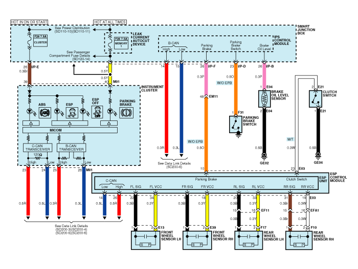
| Circuit Diagram - ESP (1) |
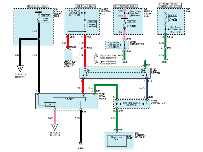
| Circuit Diagram - ESP (2) |
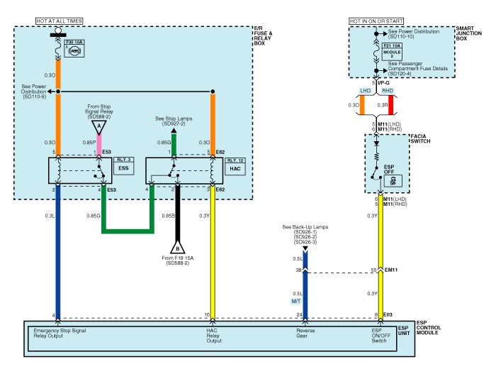
| Circuit Diagram - ESP (3) |
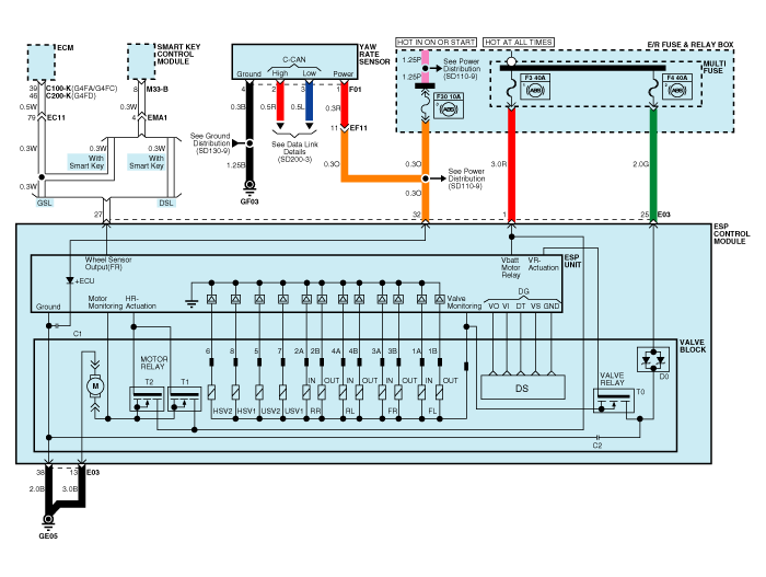
| Circuit Diagram - ESP (4) |
| ESP Connector Input/ Out put |

|
Wire No. |
Designation |
Current |
max.permissible wire resistance R_L (mΩ) |
|
|
max |
min |
|||
|
13 |
Ground for recirculation pump |
39 A |
10 A |
- |
|
38 |
Ground for solenoid valves and ECU |
15 A |
2 A |
- |
|
1 |
Voltage supply for pump motor |
39 A |
10 A |
- |
|
25 |
Voltage supply for solenoid valves |
15 A |
2 A |
- |
|
32 |
Voltage for hybrid ECU |
1 A |
500 mA |
60 |
|
22,6,20,31 |
signal wheel speed sensor FL, FR, RL,RR |
16.8 mA |
5.9 mA |
250 |
|
34,18,33,19 |
Voltage supply for the active wheel speed sensor FL,FR, RL, RR |
16.8 mA |
5.9 mA |
250 |
|
30 |
Brake light switch (Signal) |
10 mA |
5 mA |
250 |
|
14 |
CAN Low |
30 mA |
20 mA |
250 |
|
26 |
CAN High |
30 mA |
20 mA |
250 |
|
27 |
Wheel speed sensor output |
Open Drain |
- |
- |
|
8 |
ESP Passive switch (Signal) |
10 mA |
5 mA |
250 |
|
4 |
ESS output signal |
200 mA |
100 mA |
150 |
|
16 |
Brake lamp actuator input signal |
200 mA |
100 mA |
150 |
|
10 |
Parking brake switch signal |
10 mA |
5 mA |
250 |
|
23 |
Clutch switch |
10 mA |
5 mA |
250 |
 Description and operation
Description of ESP
Optimum driving safety now has a name : ESP, the Electronic Stability Program.
ESP recognizes critical driving conditions, such as panic reactions in dange ...
 Troubleshooting
Failure Diagnosis
1.
In principle, ESP and TCS controls are prohibited in case of ABS failure.
2.
When ESP or TCS fails, only the fai ...
Other information:
Kia Cee'd JD Owners Manual: Multi fuse
If the multi fuse is blown, it must be
removed as follows:
1. Turn off the engine.
2. Disconnect the negative battery cable.
3. Remove the fuse panel on the right
side in the engine compartment.
4. Remove the nuts shown in the picture
above.
5. Replace the fuse with a new one of the
s ...
Kia Cee'd JD Service Manual: Rear Door Latch Repair procedures
Replacement
1.
Remove the rear door module.
(Refer to Rear Door - "Rear Door Module")
2.
Remove the rear door outside handle base (A) by pushing in the lock
pins located in the back.
3. ...
© 2017-2025 www.kceed.com
