Kia Cee'd: ABS(Anti-Lock Brake System) / Schematic diagrams
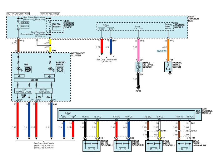
| Circuit Diagram - ABS (1) |

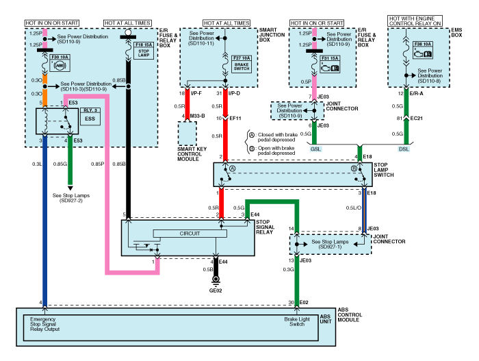
| Circuit Diagram - ABS (2) |

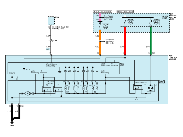
| Circuit Diagram - ABS (3) |


|
Wire No. |
Designation |
Current |
max.permissible wire resistance R_L (mΩ) |
|
|
max |
min |
|||
|
13 |
Ground for recirculation pump |
39 A |
10 A |
- |
|
38 |
Ground for solenoid valves and ECU |
15 A |
2 A |
- |
|
1 |
Voltage supply for pump motor |
39 A |
10 A |
- |
|
25 |
Voltage supply for solenoid valves |
15 A |
2 A |
- |
|
32 |
Voltage for hybrid ECU |
1 A |
500 mA |
60 |
|
22,6,20,31 |
signal wheel speed sensor FL, FR, RL,RR |
16.8 mA |
5.9 mA |
250 |
|
34,18,33,19 |
Voltage supply for the active wheel speed sensor FL,FR, RL, RR |
16.8 mA |
5.9 mA |
250 |
|
30 |
Brake light switch (Signal) |
10 mA |
5 mA |
250 |
|
14 |
CAN Low |
30 mA |
20 mA |
250 |
|
26 |
CAN High |
30 mA |
20 mA |
250 |
|
27 |
Wheel speed sensor output |
Open Drain |
- |
- |
|
Connector terminal |
Specification |
Condition |
|
|
Number |
Description |
||
|
13 |
Ground for recirculation pump |
Current range: Min.10A Max. 39A |
Always |
|
38 |
Ground for solenoid valves and ECU |
Current range: Min.2A Max. 15A |
Always |
|
1 |
Voltage supply for pump motor |
Battery voltage |
Always |
|
25 |
Voltage supply for solenoid valves |
||
|
34 |
Voltage supply for the active wheel speed sensor FL,FR, RL, RR |
Battery voltage |
IG On |
|
18 |
|||
|
33 |
|||
|
19 |
|||
|
22 |
signal wheel speed sensor FL, FR, RL,RR |
Voltage(High) : 0.26 ~ 0.37 V Voltage (Low) : 0.13 ~ 0.18 V |
On driving |
|
6 |
|||
|
20 |
|||
|
31 |
|||
|
32 |
Voltage for hybrid ECU |
Battery voltage |
KEY ON/OFF |
|
30 |
Brake light switch |
Voltage (High) ≥ 4.5 * IG ON Voltage (Low) ≤ 2.0 * IG ON |
Brake On/Off |
|
|
Description |
Abbreviation |
Unit |
Remarks |
|
1 |
Vehicle speed sensor |
VEH. SPD |
Km/h |
|
|
2 |
Battery voltage |
BATT. VOL |
V |
|
|
3 |
FL Wheel speed sensor |
FL WHEEL |
Km/h |
|
|
4 |
FR Wheel speed sensor |
FR WHEEL |
Km/h |
|
|
5 |
RL Wheel speed sensor |
RL WHEEL |
Km/h |
|
|
6 |
RR Wheel speed sensor |
RR WHEEL |
Km/h |
|
|
7 |
ABS Warning lamp |
ABS LAMP |
- |
|
|
8 |
EBD Warning lamp |
EBD LAMP |
- |
|
|
9 |
Brake Lamp |
B/LAMP |
- |
|
|
10 |
Pump relay state |
PUMP RLY |
- |
|
|
11 |
Valve relay state |
VALVE RLY |
- |
|
|
12 |
Motor |
MOTOR |
- |
|
|
13 |
Front Left valve(IN) |
FL INLET |
- |
|
|
14 |
Front Right valve (IN) |
FR INLET |
- |
|
|
15 |
Rear Left valve (IN) |
RL INLET |
- |
|
|
16 |
Rear Right valve (IN) |
RR INLET |
- |
|
|
17 |
Front Left valve (OUT) |
FL OUTLET |
- |
|
|
18 |
Front Right valve (OUT) |
FR OUTLET |
- |
|
|
19 |
Rear Left valve(OUT) |
RL OUTLET |
- |
|
|
20 |
Rear Right valve (OUT) |
RR OUTLET |
- |
|
 Description and operation
Description
This specification applies to HCU(Hydraulic Control Unit) and ECU(Electronic
Control Unit) of the HECU.(Hydraulic and Electronic Control Unit)
This specification is ...
 Troubleshooting
Standard Flow of Diagnostic Troubleshooting
Notes With Regard To Diagnosis
The phenomena listed in the following table are not abnormal.
Phenomenon
Ex ...
Other information:
Ford Escape 2020-2026 Owners Manual: Clearing the Garage Door Opener. Reprogramming the Garage Door Opener. Garage Door Opener Radio Frequencies
Clearing the Garage Door Opener
Press and hold the outer two function
buttons simultaneously for
approximately 10 seconds until the
indicator light above the buttons
flashes rapidly.
When the indicator light flashes,
release the buttons.
Note: You cannot erase individual buttons.
Repr ...
Kia Cee'd JD Service Manual: Multimedia Jack Schematic diagrams
Circuit Diagram
No
Terminal Description
Condition
Specified Condition
1
USB /iPod power
USB/iPod device is inserted
4.9V ~ 5.1V
2
USB D-
...
