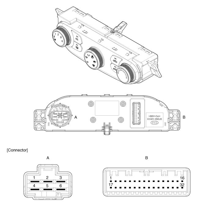
Kia Cee'd: Controller / Heater & A/C Control Unit (MANUAL) Components and components location
Kia Cee'd JD Service Manual / Heating,Ventilation, Air Conditioning / Controller / Heater & A/C Control Unit (MANUAL) Components and components location
| Components |

Connector Pin Function
|
Connector |
Pin
No. |
Gasoline |
Diesel |
|
Function |
Function |
||
|
A |
1 |
Low |
Low |
|
2 |
Common |
Common |
|
|
3 |
High |
High |
|
|
4 |
Middle Low |
Middle Low |
|
|
5 |
Middle High |
Middle High |
|
|
6 |
Ground |
Ground |
|
|
B |
1 |
Battery |
Battery |
|
2 |
Ignition 2 |
Ignition 2 |
|
|
3 |
Ignition 1 |
Ignition 1 |
|
|
4 |
HTD (Rear Defrost Indicator) |
HTD |
|
|
5 |
Detent Out (+) |
Detent Out (+) |
|
|
6 |
Evaporator Temperature Sensor (+) |
Evaporator Temperature Sensor (+) |
|
|
7 |
Ambient Temperature Sensor (+) |
Ambient Temperature Sensor (+) |
|
|
8 |
Mode Actuator Feedback |
Mode Actuator Feedback |
|
|
9 |
Temperature Actuator Feedback |
Temperature Actuator Feedback |
|
|
10 |
Intake Actuator Feedback |
Intake Actuator Feedback |
|
|
11 |
Rear Defog Switch |
Rear Defog Switch |
|
|
12 |
- |
PTC ON Signal |
|
|
13 |
PTC Relay |
PTC Relay 2 |
|
|
14 |
_ |
PTC Relay 3 |
|
|
15 |
Sensor Ground |
Sensor Ground |
|
|
16 |
Ground |
Ground |
|
|
17 |
Tail Lamp (+) |
Tail Lamp (+) |
|
|
18 |
Sensor REF (+5V) |
Sensor REF (+5) |
|
|
19 |
ECV + |
ECV + |
|
|
20 |
ECV - (Ground) |
ECV - (Ground) |
|
|
21 |
Mode Actuator (Vent) |
Mode Actuator (Vent) |
|
|
22 |
Mode Actuator (Defog) |
Mode Actuator (Defog) |
|
|
23 |
Temperature Actuator (Cool) |
Temperature Actuator (Cool) |
|
|
24 |
Temperature Actuator (Warm) |
Temperature Actuator (Warm) |
|
|
25 |
Intake Actuator (Fresh) |
Intake Actuator (Fresh) |
|
|
26 |
Intake Actuator (Recirculation) |
Intake Actuator (Recirculation) |
|
|
27 |
C-CAN (High) |
C-CAN (High) |
|
|
28 |
C-CAN (Low) |
C-CAN (Low) |
|
|
29 |
Max. Blower ON Signal |
Max. Blower ON Signal |
|
|
30 |
- |
- |
|
|
31 |
Blower ON Signal To Common |
Blower ON Signal To Common |
|
|
32 |
Rheostat (ILL-) |
Rheostat (ILL-) |
 Controller
...
 Heater & A/C Control Unit (MANUAL) Repair procedures
Replacement
•
When prying with a flat-tip screwdriver, wrap it with protective
...
Other information:
Kia Cee'd JD Service Manual: Repair procedures
Service Point Target Auto
Calibration (SPTAC)
This procedure provides a way to calibrate the camera by having the service
technician align the car to a well lit simulated straight road target; preferably
wall mounted.
The LDWS camera will have a "System Out of Cal ...
Kia Cee'd JD Service Manual: TPMS Receiver Schematic diagrams
Circuit Diagram
Hamess Connector
Pin No.
Discription
1
Battery ECU
2
Ignition ON
3
CAN_HIGH
4
CAN_LOW
...
© 2017-2025 www.kceed.com

