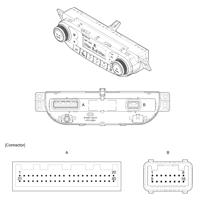
Kia Cee'd: Controller / Heater & A/C Control Unit (DATC) Components and components location
Kia Cee'd JD Service Manual / Heating,Ventilation, Air Conditioning / Controller / Heater & A/C Control Unit (DATC) Components and components location
| Components |

Gasline
Connector Pin Function
|
Connector |
Pin
No. |
Function |
Connector |
Pin
No. |
Function |
|
A |
1 |
Tail Lamp (+) |
A |
29 |
Humidity (PWM) |
|
2 |
Sensor REF (+5V) |
30 |
Photo Sensor (-) - Left |
||
|
3 |
C-CAN (High) |
31 |
- |
||
|
4 |
C-CAN (Low) |
32 |
Photo Sensor (-) - Right |
||
|
5 |
Mode Actuator (Vent) |
33 |
ECV + |
||
|
6 |
Mode Actuator (Defog) |
34 |
ECV - (Ground) |
||
|
7 |
Mode Actuator Feedback |
35 |
Fet (Gate) |
||
|
8 |
Intake Actuator (Fresh) |
36 |
Duct Sensor (+) - Vent |
||
|
9 |
Intake Actuator (Recirculation) |
37 |
Duct Sensor (+) - Floor |
||
|
10 |
Intake Actuator Feedback |
38 |
- |
||
|
11 |
K-Line |
39 |
- |
||
|
12 |
HTD (Rear Defrost Indicator) |
40 |
- |
||
|
13 |
Rear Defog Switch |
B |
1 |
Ground |
|
|
14 |
Temperature Actuator (Cool) - Driver |
2 |
Sensor Ground |
||
|
15 |
Temperature Actuator (Warm) - Driver |
3 |
Fet (Drain Feedback) |
||
|
16 |
Temperature Actuator Feedback - Driver |
4 |
Ionizer Diagnosis |
||
|
17 |
- |
5 |
Clean Signal |
||
|
18 |
- |
6 |
ION Signal |
||
|
19 |
- |
7 |
Ignition 1 |
||
|
20 |
Rheostat (ILL-) |
8 |
Ignition 2 |
||
|
21 |
Detent Out (+) |
9 |
Ground |
||
|
22 |
- |
10 |
- |
||
|
23 |
PTC Relay |
11 |
Temperature Actuator Feedback - Passenger |
||
|
24 |
- |
12 |
Temperature Actuator (Cool) - Passenger |
||
|
25 |
- |
13 |
Temperature Actuator (Warm) - Passenger |
||
|
26 |
- |
14 |
Blower Motor (+) |
||
|
27 |
Ambient Temperature Sensor (+) |
15 |
- |
||
|
28 |
Evaporator Temperature Sensor (+) |
16 |
Battery |
Diesel
Connector Pin Function
|
Connector |
Pin
No. |
Function |
Connector |
Pin
No. |
Function |
|
A |
1 |
Tail Lamp (+) |
A |
29 |
Humidity (PWM) |
|
2 |
Sensor REF (+5V) |
30 |
Photo Sensor (-) - Left |
||
|
3 |
C-CAN (High) |
31 |
- |
||
|
4 |
C-CAN (Low) |
32 |
Photo Sensor (-) - Right |
||
|
5 |
Mode Actuator (Vent) |
33 |
ECV + |
||
|
6 |
Mode Actuator (Defog) |
34 |
ECV - (Ground) |
||
|
7 |
Mode Actuator Feedback |
35 |
Fet (Gate) |
||
|
8 |
Intake Actuator (Fresh) |
36 |
Duct Sensor (+) - Vent |
||
|
9 |
Intake Actuator (Recirculation) |
37 |
Duct Sensor (+) - Floor |
||
|
10 |
Intake Actuator Feedback |
38 |
- |
||
|
11 |
K-Line |
39 |
- |
||
|
12 |
HTD (Rear Defrost Indicator) |
40 |
- |
||
|
13 |
Rear Defog Switch |
B |
1 |
Ground |
|
|
14 |
Temperature Actuator (Cool) - Driver |
2 |
Sensor Ground |
||
|
15 |
Temperature Actuator (Warm) - Driver |
3 |
Fet (Drain Feedback) |
||
|
16 |
Temperature Actuator Feedback - Driver |
4 |
Ionizer Diagnosis |
||
|
17 |
- |
5 |
Clean Signal |
||
|
18 |
- |
6 |
ION Signal |
||
|
19 |
- |
7 |
Ignition 1 |
||
|
20 |
Rheostat (ILL-) |
8 |
Ignition 2 |
||
|
21 |
Detent Out (+) |
9 |
Ground |
||
|
22 |
- |
10 |
- |
||
|
23 |
PTC Relay 2 |
11 |
Temperature Actuator Feedback - Passenger |
||
|
24 |
PTC Relay 3 |
12 |
Temperature Actuator (Cool) - Passenger |
||
|
25 |
PTC ON Signal |
13 |
Temperature Actuator (Warm) - Passenger |
||
|
26 |
- |
14 |
Blower Motor (+) |
||
|
27 |
Ambient Temperature Sensor (+) |
15 |
- |
||
|
28 |
Evaporator Temperature Sensor (+) |
16 |
Battery |
 Heater & A/C Control Unit (MANUAL) Repair procedures
Replacement
•
When prying with a flat-tip screwdriver, wrap it with protective
...
 Heater & A/C Control Unit (DATC) Repair procedures
Self Diagnosis
1.
Self-diagnosis process
2.
How to read self-diagnostic code
After the display the panel blinks three t ...
Other information:
Kia Cee'd JD Owners Manual: Smart key precautions
✽ NOTICE
If, for some reason, you happen to lose
your smart key, you will not be able to
start the engine. Tow the vehicle, if
necessary, we recommend that you
contact an authorized Kia dealer.
A maximum of 2 smart keys can be
registered to a single vehicle. If you
lose a s ...
Kia Cee'd JD Service Manual: Description and operation
Description
TREAD Lamp
–
Tire Under Inflation / Leak Warning.
1.
Turn on condition
•
When tire pressure is below allowed threshold
•
Wh ...
© 2017-2025 www.kceed.com

