Kia Cee'd: Engine Control System / Components and components location
Kia Cee'd JD Service Manual / Fuel System / Engine Control System / Components and components location
| Components Location |
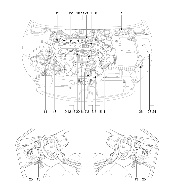
| 1. Engine Control Module (ECM)
2. Manifold Absolute Pressure Sensor (MAPS) 3. Intake Air Temperature Sensor (IATS) 4. Engine Coolant Temperature Sensor (ECTS) 5. Throttle Position Sensor (TPS) [integrated into ETC Module] 6. Crankshaft Position Sensor (CKPS) 7. Camshaft Position Sensor (CMPS) [Bank 1 / Intake] 8. Camshaft Position Sensor (CMPS) [Bank 1 / Exhaust] 9. Knock Sensor (KS) 10. Heated Oxygen Sensor (HO2S) [Bank 1 / Sensor 1] 11. Heated Oxygen Sensor (HO2S) [Bank 1 / Sensor 2] 12. Rail Pressure Sensor (RPS) 13. Accelerator Position Sensor (APS) |
14. A/C Pressure Transducer (APT)
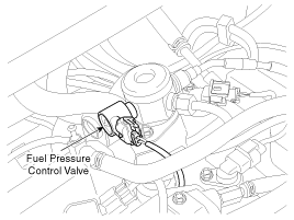
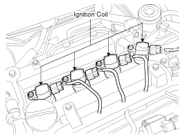
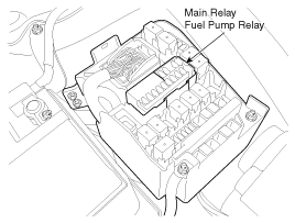
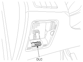
15. ETC Motor [integrated into ETC Module] 16. Injector 17. Purge Control Solenoid Valve (PCSV) 18. CVVT Oil Control Valve (OCV) [Bank 1 / Intake] 19. CVVT Oil Control Valve (OCV) [Bank 1 / Exhaust] 20. Variable Intake Solenoid (VIS) Valve 21. Fuel Pressure Control Valve (FPCV) 22. Ignition Coil 23. Main Relay 24. Fuel Pump Relay 25. Data Link Connector (DLC) [16-Pin] 26. Multi-Purpose Check Connector [20-Pin] |
|
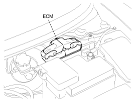
1. Engine Control Module (ECM) |
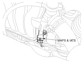
2. Manifold Absolute Pressure Sensor (MAPS) 3. Intake Air Temperature Sensor (IATS) |
|
|
|
|
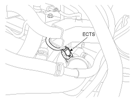
4. Engine Coolant Temperature Sensor (ECTS) |
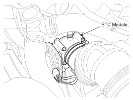
5. Throttle Position Sensor (TPS) 15. ETC Motor |
|
|
|
|
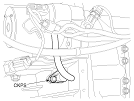
6. Crankshaft Position Sensor (CKPS) |
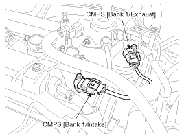
7. Camshaft Position Sensor (CMPS) [Bank 1 / Intake] 8. Camshaft Position Sensor (CMPS) [Bank 1 / Exhaust] |
|
|
|
|
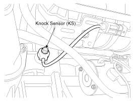
9. Knock Sensor (KS) |
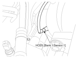
10. Heated Oxygen Sensor (HO2S) [Bank 1/Sensor 1] |
|
|
|
|
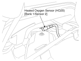
11. Heated Oxygen Sensor (HO2S) [Bank 1/Sensor 2] |
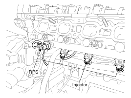
12. Rail Pressure Sensor (RPS) 16. Injector |
|
|
|
|
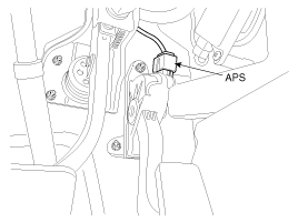
13. Accelerator Position Sensor (APS) |
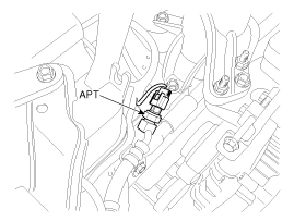
14. A/C Pressure Transducer (APT) |
|
|
|
|
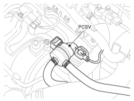
17. Purge Control Solenoid Valve (PCSV) |
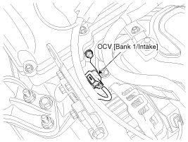
18. CVVT Oil Control Valve (OCV) [Bank 1 / Intake] |
|
|
|
|
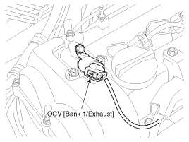
19. CVVT Oil Control Valve (OCV) [Bank 1 / Exhaust] |
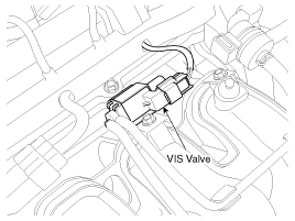
20. Variable Intake Solenoid (VIS) Valve |
|
|
|
|
21. Fuel Pressure Control Valve (FPCV) |
22. Ignition Coil |
|
|
|
|
23. Main Relay 24. Fuel Pump Relay |
25. Data Link Connector (DLC) [16-Pin] |
|
|
|
|
26. Multi-Purpose Check Connector [20-Pin] |
|
|
|
 Description and operation
OBD-II review
1. Overview
The California Air Resources Board (CARB) began regulation of On Board Diagnostics
(OBD) for vehicles sold in California beginning with the 1988 model ...
 Engine Control Module (ECM) Schematic diagrams
ECM (Engine Control Module)
ECM Harness Connector
ECM Terminal Function
Connector [C200-A]
Pin No.
Description
...
Other information:
Kia Cee'd JD Service Manual: Shift Lever Components and components location
Components
1. Shift lever assembly
2. Shift cable assembly
3. Retainer
4. Bolt
5. Nut
6. Manual control lever
...
Kia Cee'd JD Owners Manual: To defog inside windshield
1. Set the fan speed to the desired
speed.
2. Select desired temperature.
3. Press the button.
4. The air conditioning will turn on
according to the detected ambient temperature
and outside (fresh) air position
will be selected automatically.
If the air conditioning is not selected
...
© 2017-2025 www.kceed.com


