Kia Cee'd: Ignition Lock Switch / Clutch Pedal Repair procedures
| Removal |
| 1. |
Remove the battery and battery tray.
G 1.6 MPI (Refer to Engine Electrical System - "Battery")
G 1.4 MPI (Refer to Engine Electrical System - "Battery")
D 1.6 TCI-U2 (Refer to Engine Electrical System - "Battery")
D 1.4 TCI-U2 (Refer to Engine Electrical System - "Battery")
G 1.6 GDI (Refer to Engine Electrical System - "Battery")
G 1.6 T-GDI (Refer to Engine Electrical System - "Battery")
|
| 2. |
Remove the ECM.
G 1.6 MPI (Refer to Engine Control / Fuel System - "Engine Control Module")
G 1.4 MPI (Refer to Engine Control / Fuel System - "Engine Control Module")
D 1.6 TCI-U2 (Refer to Engine Control / Fuel System - "Engine Control
Module")
D 1.4 TCI-U2 (Refer to Engine Control / Fuel System - "Engine Control
Module")
G 1.6 GDI (Refer to Engine Control / Fuel System - "Engine Control Module")
G 1.6 T-GDI (Refer to Engine Control / Fuel System - "Engine Control
Module")
|
| 3. |
The case of diesel vehicle, remove the fuel filter.
D 1.6 TCI-U2 (Refer to Engine Control / Fuel System - "Fuel Filter")
D 1.4 TCI-U2 (Refer to Engine Control / Fuel System - "Fuel Filter")
|
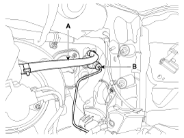
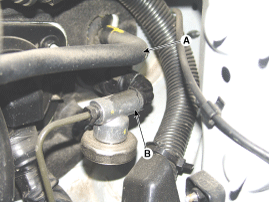
| 4. |
Disconnect the clutch tube (B) and reservoir hose (A) from the clutch
master cylinder.
[Gasoline]
[Diesel]
|

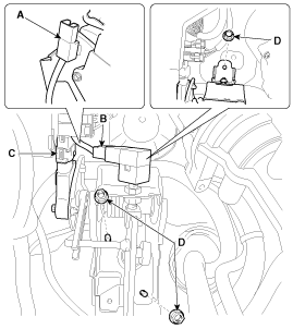
| 5. |
Disconnect the ignition lock switch connector (A) and clutch switch
connector (B) and EPB stroke sensor connector (C).
|
| 6. |
Remove the clutch pedal mounting nuts (D-3ea).
|
| 7. |
Remove the clutch pedal and master cylinder together.
|
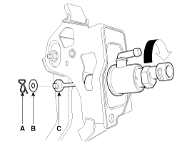
| 8. |
Remove the master cylinder from the clutch pedal.
|
| Installation |
| 1. |
Install in the reverse order of removal.
|
| 2. |
After be equipped, perform bleeding air procedure in clutch release
cylinder after pouring the brake fluid.
(Refer to Clutch System - "Clutch release cylinder")
|
 Clutch Pedal Components and components location
Components
1. Master cylinder
2. Ignition lock switch
3. Clutch switch
4. Pedal pad
...

Other information:
Kia Cee'd JD Service Manual: Injector Description and operation
Description
The GDI injector is similar to a standard injector, but sprays fuel at a much
higher pressure directly into the combustion chamber and has a swirl disc to
get the fuel swirling as it exits the nozzle. This aids in atomization of the
fuel.The ECM controls both the ...
Kia Cee'd JD Owners Manual: Easy access function
The system will move the driver's seat
automatically as follows:
Without smart key system
- It will move the driver’s seat rearward
when the ignition key is removed and
front driver’s door is opened.
- It will move the driver’s seat forward
when the ignition key is inserted. ...
© 2017-2025 www.kceed.com
