Kia Cee'd: Engine Control System / Engine Control Module (ECM) Repair procedures
Kia Cee'd JD Service Manual / Fuel System / Engine Control System / Engine Control Module (ECM) Repair procedures
| Removal |
When replacing the ECM, the vehicle equipped with the immobilizer must
be performed procedure as below.
[In the case of installing used ECM]
1) Perform "ECM Neutral mode" procedure with GDS.
(Refer to Body Electrical System - "Immobilizer System")
2) After finishing "ECM Neutral mode", perform "Key teaching" procedure
with GDS.
(Refer to Body Electrical System - "Immobilizer System")
[In the case of installing new ECM]
Perform "Key teaching" procedure with GDS.
(Refer to Body Electrical System - "Immobilizer System")
|

When replacing the ECM, the vehicle equipped with the smart key system
(Button start) must be performed procedure as below.
[In the case of installing used ECM]
1) Perform "ECM Neutral mode" procedure with GDS.
(Refer to Body Electrical System - "Immobilizer System")
2) After finishing "ECM Neutral mode", insert the key (or press the
start button) and turn it to the IGN ON and OFF position. Then the ECM
learns the smart key information automatically.
[In the case of installing new ECM]
Insert the key (or press the start button) and turn it to the IGN ON
and OFF position. Then the ECM learns the smart key information automatically.
|
| 1. |
Turn ignition switch OFF and disconnect the negative (-) battery cable.
|
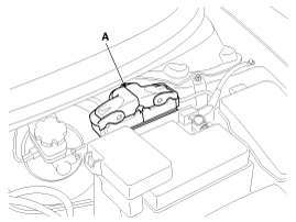
| 2. |
Disconnect the ECM Connector (A).
|
| 3. |
Remove the battery.
(Refer to Engine Electrical System - "Battery")
|
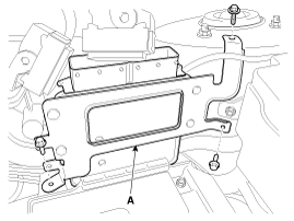
| 4. |
Remove the mounting bolts and nut, and then remove the ECM bracket assembly
(A).
|
| Installation |
When replacing the ECM, the vehicle equipped with the immobilizer must
be performed procedure as below.
[In the case of installing used ECM]
1) Perform "ECM Neutral mode" procedure with GDS.
(Refer to Body Electrical System - "Immobilizer System")
2) After finishing "ECM Neutral mode", perform "Key teaching" procedure
with GDS.
(Refer to Body Electrical System - "Immobilizer System")
[In the case of installing new ECM]
Perform "Key teaching" procedure with GDS.
(Refer to Body Electrical System - "Immobilizer System")
|
When replacing the ECM, the vehicle equipped with the smart key system
(Button start) must be performed procedure as below.
[In the case of installing used ECM]
1) Perform "ECM Neutral mode" procedure with GDS.
(Refer to Body Electrical System - "Immobilizer System")
2) After finishing "ECM Neutral mode", insert the key (or press the
start button) and turn it to the IGN ON and OFF position. Then the ECM
learns the smart key information automatically.
[In the case of installing new ECM]
Insert the key (or press the start button) and turn it to the IGN ON
and OFF position. Then the ECM learns the smart key information automatically.
|
| 1. |
Installation is reverse of removal.
|
| ECM Problem Inspection Procedure |
| 1. |
TEST ECM GROUND CIRCUIT: Measure resistance between ECM and chassis
ground using the backside of ECM harness connector as ECM side check
point. If the problem is found, repair it.
|
| 2. |
TEST ECM CONNECTOR: Disconnect the ECM connector and visually check
the ground terminals on ECM side and harness side for bent pins or poor
contact pressure. If the problem is found, repair it.
|
| 3. |
If problem is not found in Step 1 and 2, the ECM could be faulty. If
so, make sure there were no DTC's before swapping the ECM with a new
one, and then check the vehicle again. If DTC's were found, examine
this first before swapping ECM.
|
| 4. |
RE-TEST THE ORIGINAL ECM: Install the original ECM (may be broken) into
a known-good vehicle and check the vehicle. If the problem occurs again,
replace the original ECM with a new one. If problem does not occur,
this is intermittent problem (Refer to “Intermittent Problem Inspection
Procedure” in Basic Inspection Procedure).
|
 Engine Control Module (ECM) Schematic diagrams
ECM (Engine Control Module)
ECM Harness Connector
ECM Terminal Function
Connector [C200-A]
Pin No.
Description
...
 ETC (Electronic Throttle Control) System Description and operation
Description
The Electronic Throttle Control (ETC) System consists of a throttle body with
an integrated control motor and throttle position sensor (TPS). Instead of the
tradition ...
Other information:
Kia Cee'd JD Owners Manual: Disarmed stage
The system will be disarmed when:
Transmitter
- The door unlock button is pressed.
- The engine is started.
- The ignition switch is in the “ON” position
for 30 seconds or more.
Smart key
- The door unlock button is pressed.
- The button of the front outside door is
pressed while carr ...
Kia Cee'd JD Owners Manual: Additional safety precautions
Never let passengers ride in the
cargo area or on top of a foldeddown
back seat. All occupants should
sit upright, fully back in their seats with
their seat belts on and their feet on the
floor.
Passengers should not move out of
or change seats while the vehicle is
moving. ...
© 2017-2026 www.kceed.com
