Kia Cee'd: Engine Room Under Cover / Engine And Transmission Assembly Repair procedures
Kia Cee'd JD Service Manual / Engine Mechanical System / Engine Room Under Cover / Engine And Transmission Assembly Repair procedures
| Removal |
|

|

| 1. |
Remove the engine cover.
|
| 2. |
Disconnect the battery negative terminal.
|
| 3. |
Remove the air duct and air cleaner assembly.
(Refer to Intake and Exhaust System - "Air Cleaner")
|
| 4. |
Disconnect the mounting bracket and then remove the battery.
(Refer to Engine Electrical System - "Battery")
|
| 5. |
Disconnect the ECM connector and then remove the battery tray.
(Refer to Engine Electrical System - "Battery")
|
| 6. |
Remove the engineroom under cover.
|
| 7. |
Loosen the drain plug and drain the coolant. Open the radiator cap to
make rapid draining.
(Refer to Cooling System - "Coolant")
|
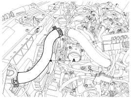
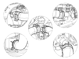
| 8. |
Remove the radiator upper hose (A) and lower hose (B).
|
| 9. |
Recover the refrigerant and then remove the high pressure pipe and low
pressure pipe.
(Refer to Heating, Ventilation Air conditioning -"Compressor")
|
| 10. |
Disconnet the wiring connector and cable from trasaxle.
|
| 11. |
Remove the ATF cooler hose.
|
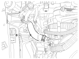
| 12. |
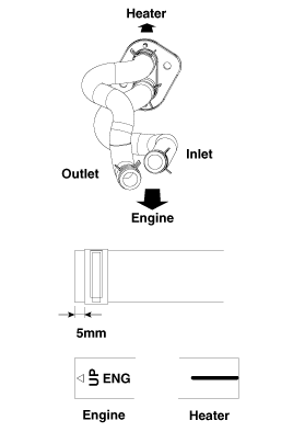
Disconnect the mounting clamp and then remove the heater hose(A).
|
| 13. |
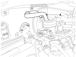
Disconnet the brake booster vacuum hose(A).
|
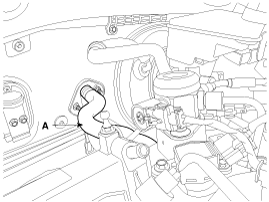
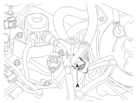
| 14. |
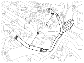
Disconnect the fuel hose(A) and PCSV(Purge control solenoid valve)(B).
|
| 15. |
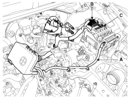
Disconnect the (+) cable(A), fuse box connector(B), EMS block(C) and
then remove the engine wiring.
|
| 16. |
Disconnect the Oxygen sensor connectors(A).
|
| 17. |
Remove the front muffler.
(Refer to Intake and Exhaust System - "Muffler")
|
| 18. |
Support the sub frame with a floor jack and then remove the sub frame
mounting bolts and nuts.
(Refer to Suspension System - “Sub Frame”)
|
| 19. |
Disconnect the ground cable, and then remove the engine suppert mounting
bracket.
(Engine and Transaxle Assembly - "Engine Mounting")
|
| 20. |
Disconnect the ground and then remove the transmission mounting bracket
bolts.
|
| 21. |
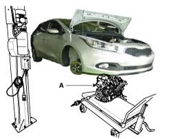
Remove the engine and transaxle assembly(A) in the forward direction
from the vehicle.
|
| Installation |
Installation is in the reverse order of removal.
Perform the following :
| • |
Adjust a shift cable.
|
| • |
Adjust the throttle cable.
|
| • |
Refill engine with engine oil.
|
| • |
Refill a transaxle with fluid.
|
| • |
Refill power steering fluid.
|
| • |
Refill a radiator and a reservoir tank with engine coolant.
|
| • |
Place a heater control knob on "HOT" position.
|
| • |
Clean battery posts and cable terminals and assemble.
|
| • |
Inspect for fuel leakage.
|
| – |
After assemble the fuel line, turn on the ignition switch (do not operate
the starter) so that the fuel pump runs for approximately two seconds
and fuel line pressurizes.
|
| – |
Repeat this operation two or three times, then check for fuel leakage
at any point in the fuel line.
|
| • |
Bleed air from the cooling system.
|
| – |
Start engine and let it run until it warms up. (until the radiator fan
operates 3 or 4 times.)
|
| – |
Turn Off the engine. Check the level in the radiator, add coolant if
needed. This will allow trapped air to be removed from the cooling system.
|
 Engine Mounting Repair procedures
Removal and Installation
[Rollroad mounting]
1.
Rollroad bracket mounting bolts and rollroad bracket (A).
Tightening torque
...
 Timing System
...
Other information:
Kia Cee'd JD Service Manual: Schematic diagrams
Block Diagram
Circuit Diagram
...
Kia Cee'd JD Owners Manual: Rear Seat Entry
(For 3-door vehicle only)
To get in or get out of the rear seat, the
driver’s or front passenger’s seat should
be folded and the seat should be slide.
Driver’s seat
Front passenger’s seat
1. Fold the front seatback by pulling up
the walk-in seat lever and then slide
the front seat forward.
2. Set th ...
© 2017-2026 www.kceed.com
