
Kia Cee'd: Rear combination light bulb replacement / Inside light (5 Door and Wagon)
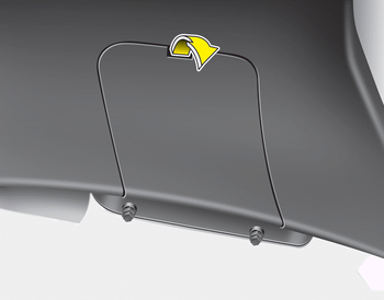
1. Turn off the engine.
2. Open the tailgate.
3. Remove the service cover using a flatblade screwdriver.
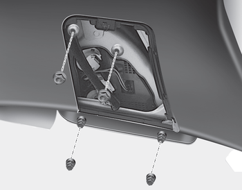
4. Loosen the retaining nuts.
5. Disconnect the power connector.
6. Remove the rear combination light assembly from the body of the vehicle.
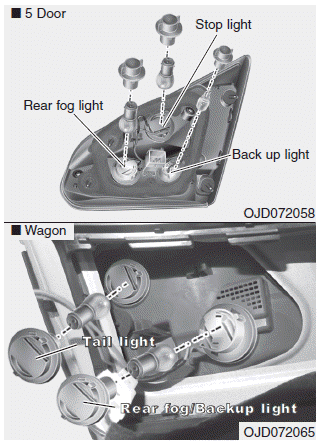
Tail light or tail and stop light (Bulb type)
7. Remove the socket from the assembly by turning the socket counterclockwise until the tabs on the socket align with the slots on the assembly.
8. Remove the bulb from the socket by pressing it in and rotating it counterclockwise until the tabs on the bulb align with the slots in the socket. Pull the bulb out of the socket.
9. Insert a new bulb by inserting it into the socket and rotating it until it locks into place.
10. Install the socket in the assembly by aligning the tabs on the socket with the slots in the assembly. Push the socket into the assembly and turn the socket clockwise.
11. Install the service cover by putting it into the service hole.
Back-up light and rear fog light (5 Door and Wagon) (if equipped)
7. Remove the socket from the assembly by turning the socket counterclockwise until the tabs on the socket align with the slots on the assembly.
8. Pull the bulb out of the socket.
9. Insert a new bulb into the socket.
10. Install the socket into the assembly by aligning the tabs on the socket with the slots on the assembly and turning the socket clockwise.
11. Reinstall the light assembly to the body of the vehicle
❈ Rear fog light is located only on the driver’s side. (for wagon)
 Outside light
Rear turn signal light and stop/tail light
1. Turn off the engine.
2. Open the tailgate.
3. Loosen the light assembly retaining
screws with a cross-tip screwdriver.
4. Remove the rear combinat ...
 Rear fog light
1. Remove the under cover by rotating
the screws.
2. Reach your hand into the back of the
rear bumper.
3. Disconnect the power connector.
4. Remove the bulb-socket from the
housing by tur ...
Other information:
: Towing a Trailer Limitations. Loading Your Trailer. Trailer Towing Hints
Towing a Trailer Limitations
The vehicle's load capacity
designation is by weight, not by
volume, so you cannot necessarily
use all available space when
loading a vehicle or trailer.
Note: Your vehicle could have
reduced performance when
operating at high altitudes and
when heavily loaded or ...
Kia Cee'd JD Service Manual: CVVT Oil Control Valve (OCV) Repair procedures
Inspection
1.
Turn the ignition switch OFF.
2.
Disconnect the OCV connector.
3.
Measure resistance between the OCV terminals 1 and 2.
4.
Check that the resistance is within t ...
