Kia Cee'd: Engine Control System / Injector Troubleshooting
| Signal Waveform |
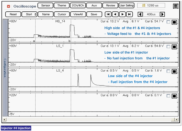
The three waveforms below are taken from the #1 and #4 injectors. The top waveform
is from the high side (feed side) of the #1 and #4 injectors, while the middle
waveform is from the low side (ground side) of the #1 injector and the bottom
waveform is from the low side of the #4 injector.
The middle waveform is the same as the top waveform because there is no ground
for the circuit. With no current flowing in the circuit, the #1 injector is
not energized and fuel does not flow.
The bottom waveform shows that ground is supplied and there is a voltage drop
across the #4 injector. With current flowing in the circuit, the #4 injector
is energized and fuel flows.

 Injector Specifications
Specification
Item
Specification
Coil Resistance (Ω)
1.5 ± 5%[20°C(68°F)]
...
 Injector Schematic diagrams
Circuit Diagram
...
Other information:
: Connecting a Trailer Precautions
WARNING: Do not adjust the spring
bars so that your vehicle's rear bumper
is higher than before attaching the trailer.
Doing so will defeat the function of the
weight-distributing hitch, which may
cause unpredictable handling, and could
result in serious personal injury.
Do not tow a trailer u ...
Kia Cee'd JD Service Manual: Special service tools
Special Service Tools
Tool Name / Number
Illustration
Description
Engine support fixture (bar)
09200-3N000
Used for holding engine assembly when removing / installing transaxle
Used ...
© 2017-2026 www.kceed.com

